Intel D815EEA2U Product Guide - Page 82
Intel D815EEA2U - P3 Socket 370 ATX Motherboard Manual
 |
UPC - 735858146135
View all Intel D815EEA2U manuals
Add to My Manuals
Save this manual to your list of manuals |
Page 82 highlights
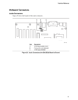
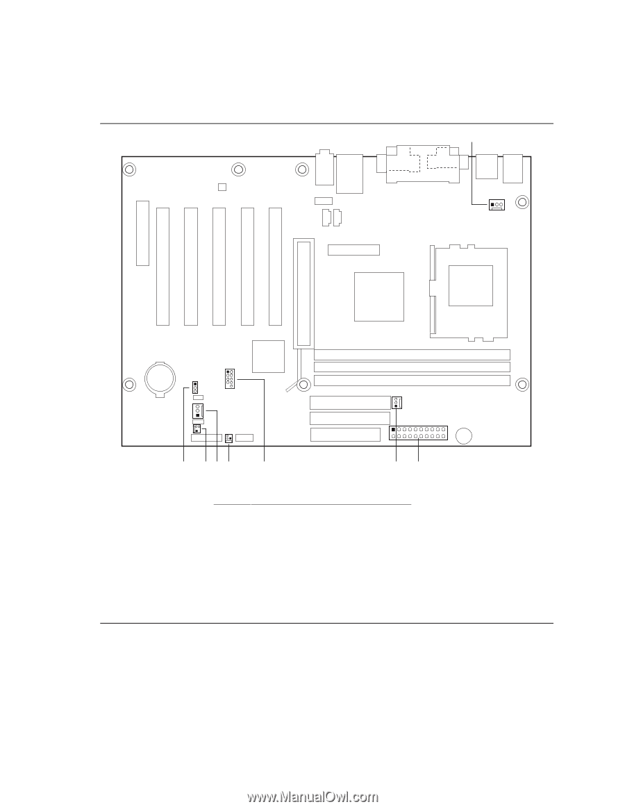
Intel Desktop Boards D815EEA2, D815EPEA2, D815EFV, and D815EPFV Product Guide Power and Hardware Control Connectors Figure 30 shows the power and hardware connectors. A 1 2 1 1 7 10 1 1 11 10 20 H GF E Item A B C D E F G H D Description Processor fan (fan 1) Power Chassis fan (fan 3) Front panel USB (optional) SCSI LED Chassis fan (fan 2) Chassis intrusion C B OM11631 Wake on LAN technology (optional) Figure 30. Power and Hardware Control Connectors (the D815EEA2 Board Is Shown) 82
-
 1
1 -
2
-
3
-
4
-
5
-
6
-
7
-
8
-
9
-
10
-
11
-
12
-
13
-
14
-
15
-
16
-
17
-
18
-
19
-
20
-
21
-
22
-
23
-
24
-
25
-
26
-
27
-
28
-
29
-
30
-
31
-
32
-
33
-
34
-
35
-
36
-
37
-
38
-
39
-
40
-
41
-
42
-
43
-
44
-
45
-
46
-
47
-
48
-
49
-
50
-
51
-
52
-
53
-
54
-
55
-
56
-
57
-
58
-
59
-
60
-
61
-
62
-
63
-
64
-
65
-
66
-
67
-
68
-
69
-
70
-
71
-
72
-
73
-
74
-
75
-
76
-
 77
77 -
 78
78 -
 79
79 -
 80
80 -
 81
81 -
 82
82 -
 83
83 -
 84
84 -
 85
85 -
 86
86 -
 87
87 -
88
-
89
-
90
-
91
-
92
-
93
-
94
-
95
-
96
 |
 |
Intel Desktop Boards D815EEA2, D815EPEA2, D815EFV, and D815EPFV Product Guide
82
Power and Hardware Control Connectors
Figure 30 shows the power and hardware connectors.
OM11631
H
B
F
D
A
1
1
1
11
10
20
1
2
10
7
1
G
E
C
Item
Description
A
Processor fan (fan 1)
B
Power
C
Chassis fan (fan 3)
D
Front panel USB (optional)
E
SCSI LED
F
Chassis fan (fan 2)
G
Chassis intrusion
H
Wake on LAN technology (optional)
Figure 30
.
Power and Hardware Control Connectors (the D815EEA2 Board Is Shown)