Intel D815EEA2U Product Guide - Page 48
Intel D815EEA2U - P3 Socket 370 ATX Motherboard Manual
 |
UPC - 735858146135
View all Intel D815EEA2U manuals
Add to My Manuals
Save this manual to your list of manuals |
Page 48 highlights
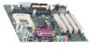
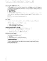
Intel Desktop Boards D815EEA2, D815EPEA2, D815EFV, and D815EPFV Product Guide Setting the BIOS Configuration Jumper CAUTION Always turn off the power and unplug the power cord from the computer before changing the jumper. Moving the jumper with the power on may result in unreliable computer operation. 3 1 J9G2 OM11628 Figure 26. BIOS Configuration Jumper Block Location (the D815EEA2 Board Is Shown) This three-pin jumper block, shown in Figure 26, enables all desktop board configurations to be done in BIOS Setup. Table 7 shows the jumper settings for the Setup program modes. Table 7. Normal Configure Recovery Jumper Settings for the BIOS Setup Program Modes Jumper Setting 1-2 2-3 None 3 1 Function/Mode Configuration The BIOS uses current configuration information and passwords for booting. After the POST runs, Setup runs automatically. The maintenance menu is displayed. The BIOS attempts to recover the BIOS configuration. A recovery diskette is required. 3 1 3 1 48
-
 1
1 -
2
-
3
-
4
-
5
-
6
-
7
-
8
-
9
-
10
-
11
-
12
-
13
-
14
-
15
-
16
-
17
-
18
-
19
-
20
-
21
-
22
-
23
-
24
-
25
-
26
-
27
-
28
-
29
-
30
-
31
-
32
-
33
-
34
-
35
-
36
-
37
-
38
-
39
-
40
-
41
-
42
-
 43
43 -
 44
44 -
 45
45 -
 46
46 -
 47
47 -
 48
48 -
 49
49 -
 50
50 -
 51
51 -
 52
52 -
 53
53 -
54
-
55
-
56
-
57
-
58
-
59
-
60
-
61
-
62
-
63
-
64
-
65
-
66
-
67
-
68
-
69
-
70
-
71
-
72
-
73
-
74
-
75
-
76
-
77
-
78
-
79
-
80
-
81
-
82
-
83
-
84
-
85
-
86
-
87
-
88
-
89
-
90
-
91
-
92
-
93
-
94
-
95
-
96
 |
 |
