Intel D815EEA2U Product Guide - Page 80
Intel D815EEA2U - P3 Socket 370 ATX Motherboard Manual
 |
UPC - 735858146135
View all Intel D815EEA2U manuals
Add to My Manuals
Save this manual to your list of manuals |
Page 80 highlights
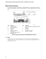
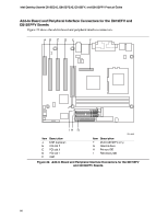
Intel Desktop Boards D815EEA2, D815EPEA2, D815EFV, and D815EPFV Product Guide Back Panel Connectors Figure 28 shows the back panel connectors on the desktop board. The back panel connectors are color-coded in compliance with PC 99 recommendations. The figure legend below lists the colors used. A C E H B D F G I J K LM OM11162 Item Description Item Description A B C D E F G PS/2 mouse, green PS/2 keyboard, purple USB port 0 USB port 1 Parallel port, burgundy VGA port, blue (D815EEA2 and D815EFV only) Serial port A, teal H I J K L M RJ-45 LAN connector with LED display (optional) USB port 2 USB port 3 Mic in, pink Audio line out, lime green Audio line in, light blue Figure 28. Back Panel Connectors (the D815EEA2 Board Is Shown) ✏ NOTE The line out connector, located on the back panel, is designed to power either headphones or amplified speakers only. Poor audio quality may occur if passive (non-amplified) speakers are connected to this output. 80
-
 1
1 -
2
-
3
-
4
-
5
-
6
-
7
-
8
-
9
-
10
-
11
-
12
-
13
-
14
-
15
-
16
-
17
-
18
-
19
-
20
-
21
-
22
-
23
-
24
-
25
-
26
-
27
-
28
-
29
-
30
-
31
-
32
-
33
-
34
-
35
-
36
-
37
-
38
-
39
-
40
-
41
-
42
-
43
-
44
-
45
-
46
-
47
-
48
-
49
-
50
-
51
-
52
-
53
-
54
-
55
-
56
-
57
-
58
-
59
-
60
-
61
-
62
-
63
-
64
-
65
-
66
-
67
-
68
-
69
-
70
-
71
-
72
-
73
-
74
-
 75
75 -
 76
76 -
 77
77 -
 78
78 -
 79
79 -
 80
80 -
 81
81 -
 82
82 -
 83
83 -
 84
84 -
 85
85 -
86
-
87
-
88
-
89
-
90
-
91
-
92
-
93
-
94
-
95
-
96
 |
 |
