Intel KD875PBZLKPAK10 Product Specification
Intel KD875PBZLKPAK10 - 10PK 875P P4-800/533MHZ Fsbatx Ddr AGP8X SATA150 5PCI Manual
 |
UPC - 735858160209
View all Intel KD875PBZLKPAK10 manuals
Add to My Manuals
Save this manual to your list of manuals |
Intel KD875PBZLKPAK10 manual content summary:
- Intel KD875PBZLKPAK10 | Product Specification - Page 1
® Desktop Board D875PBZ Technical Product Specification April 2003 Order Number: C31765-001 The Intel® Desktop Board D875PBZ may contain design defects or errors known as errata that may cause the product to deviate from published specifications. Current characterized errata - Intel KD875PBZLKPAK10 | Product Specification - Page 2
characteristics of any features or instructions marked "reserved" or "undefined." Intel reserves these for future definition 44-0-1793-421-333, other Countries 708-296-9333. Intel and Pentium are registered trademarks of Intel Corporation or its subsidiaries in the United States and other countries - Intel KD875PBZLKPAK10 | Product Specification - Page 3
This Technical Product Specification (TPS) specifies the Intel® Desktop Board D875PBZ layout, components, connectors, Desktop Board D875PBZ A map of the resources of the Desktop Board D875PBZ The features supported by the BIOS Setup program The contents of the BIOS Setup program's menus and submenus - Intel KD875PBZLKPAK10 | Product Specification - Page 4
Intel Desktop Board D875PBZ Technical Product Specification Other Common Notation # (NxnX) GB GB/sec KB Kbit kbits/sec MB MB/sec Mbit Mbits/sec xxh x.x V * Used - Intel KD875PBZLKPAK10 | Product Specification - Page 5
13 1.1.3 Board Layout 14 1.1.4 Block Diagram 15 1.2 Online Support ...16 1.3 Operating System Support 16 1.4 Design Specifications 17 1.5 Processor ...20 1.6 System Memory ...21 1.6.1 Memory Features 21 1.6.2 Memory Configurations 23 1.7 Intel® 875P Chipset ...28 1.7.1 AGP ...29 1.7.2 USB...29 - Intel KD875PBZLKPAK10 | Product Specification - Page 6
Intel Desktop Board D875PBZ Technical Product Specification 2 Technical Reference 2.1 Introduction...49 2.2 Memory Resources ...49 86 3.3.2 PCI IDE Support 86 3.4 System Management BIOS (SMBIOS 87 3.5 Legacy USB Support 88 3.6 BIOS Updates ...88 3.6.1 Language Support 89 3.6.2 Custom Splash - Intel KD875PBZLKPAK10 | Product Specification - Page 7
Without Attached Devices 90 3.8.4 Changing the Default Boot Device During POST 91 3.9 Fast Booting Systems with Intel® Rapid BIOS Boot 91 3.9.1 Peripheral Selection and Configuration 91 3.9.2 Intel Rapid BIOS Boot 92 3.10 BIOS Security Features 93 4 BIOS Setup Program 4.1 Introduction...95 - Intel KD875PBZLKPAK10 | Product Specification - Page 8
Mode 26 7. Examples of Single Channel configuration without Dynamic Mode 27 8. Intel 875P Chipset Block Diagram 28 9. Back Panel Audio Connector Options for Flex 3. Specifications ...17 4. Supported System Bus Frequency and Memory Speed Combinations 21 5. Supported Memory Configurations 22 6. - Intel KD875PBZLKPAK10 | Product Specification - Page 9
23. ATAPI CD-ROM Connector 62 24. Rear Chassis Fan Connector 64 25. ATX12V Power Connector 64 26. Voltage Regulator Fan Connector 64 27. Processor Fan Connector 64 28. Main Power Connector 65 29. Front Chassis Fan Connector 65 30. Chassis Intrusion Connector 65 31. SCSI Hard Drive Activity - Intel KD875PBZLKPAK10 | Product Specification - Page 10
Intel Desktop Board D875PBZ Technical Product Specification 64. Fan Control Configuration Submenu 114 65. Hardware Monitoring Display 115 66. Security Menu ...116 67. Power Menu ...117 - Intel KD875PBZLKPAK10 | Product Specification - Page 11
1 Product Description What This Chapter Contains 1.1 Overview ...12 1.2 Online Support ...16 1.3 Operating System Support 16 1.4 Design Specifications 17 1.5 Processor ...20 1.6 System Memory ...21 1.7 Intel® 875P Chipset ...28 1.8 I/O Controller ...32 1.9 Audio Subsystem (Optional 34 1.10 LAN - Intel KD875PBZLKPAK10 | Product Specification - Page 12
.52 inches by 9.6 inches [292.61 millimeters by 243.84 millimeters]) Processor Memory Chipset Video Audio USB Peripheral Interfaces Expansion Capabilities I/O Control LAN Hardware Monitor Subsystem Support for an Intel® Pentium® 4 processor in an mPGA478 socket with a 533/800 MHz system bus • Four - Intel KD875PBZLKPAK10 | Product Specification - Page 13
Product Description Table 1. Feature Summary (continued) BIOS • Intel/AMI BIOS (resident in the Intel 82802AC FWH) • Support for Advanced Configuration and Power Interface (ACPI), Plug and Play, and SMBIOS Instantly Available PC Technology • Support for PCI Local Bus Specification Revision 2.2 - Intel KD875PBZLKPAK10 | Product Specification - Page 14
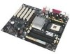
device G Rear chassis fan H Back panel connectors I +12 V power connector (ATX12V) J Voltage regulator fan K mPGA478 processor socket L Processor fan connector M Intel 82875P Memory Controller Hub (MCH) N DIMM channel A O DIMM channel B P I/O controller OM15883 Q Power connector R Diskette drive - Intel KD875PBZLKPAK10 | Product Specification - Page 15
of the Desktop Board D875PBZ. = connector or socket Parallel ATA IDE Connectors (2) Parallel ATA IDE Interface mPGA478 Processor Socket System Bus (533/800 MHz) LAN Connector Intel 82547EI PLC Device CSA Interface USB LPC Bus I/O Controller LPC Bus Back Panel/ Front Panel USB Ports Serial - Intel KD875PBZLKPAK10 | Product Specification - Page 16
Board D875PBZ Processor data sheets ICH5-R addressing Custom splash screens Audio software and utilities LAN software and drivers Visit this World Wide Web site: http://www.intel.com/design/motherbd http://support.intel.com/support/motherboards/desktop http://developer.intel.com/design/motherbd - Intel KD875PBZLKPAK10 | Product Specification - Page 17
Supply Design Guide Boot Integrity Services (BIS) Application Programming Interface (API) Version, Revision Date, and Ownership Revision 2.2, September 2000, Intel Corporation. Version 2.0a, March 31, 2002, Compaq Computer Corporation, Intel Corporation, Microsoft Corporation, Phoenix Technologies - Intel KD875PBZLKPAK10 | Product Specification - Page 18
. Revision 0.9, September 27, 2001, Intel Corporation. Revision 1.0, March 12, 2002, Intel Corporation. Version 1.7, 1997, Institute of Electrical html http://www.phoenix.com/en/ support/download/ product+documentation/ platform_system_ software.htm http://www.intel.com/ design/chipsets/industry/ lpc - Intel KD875PBZLKPAK10 | Product Specification - Page 19
Interface Design Guide Universal Serial Bus Specification Version, Revision Date and Ownership Version 2.1, September 20, 1999, Intel Corporation. Revision 1.0, August 29, 2001, APT Technologies, Inc., Dell Computer Corporation, IBM Corporation, Intel Corporation, Maxtor Corporation, Seagate - Intel KD875PBZLKPAK10 | Product Specification - Page 20
board. The board is designed to support Intel Pentium 4 processors in an mPGA478 processor socket with a 533/800 MHz system bus. See the Intel web site listed below for the most up-to-date list of supported processors. For information about... Supported processors for the D875PBZ board Refer to - Intel KD875PBZLKPAK10 | Product Specification - Page 21
Detect • DDR400 and DDR333 SDRAM DIMMs Table 4 lists the supported system bus frequency and memory speed combinations. Table 4. Supported System Bus Frequency and Memory Speed Combinations To use this type of DIMM... The processor's system bus frequency must be... DDR400 800 MHz DDR333 800 - Intel KD875PBZLKPAK10 | Product Specification - Page 22
Intel Desktop Board D875PBZ Technical Product Specification Table 5 lists the supported DIMM configurations. Table 5. Supported Memory Configurations DIMM Capacity DDR SDRAM Configuration Density DDR SDRAM Organization Number of DDR Front-side/Back-side SDRAM Devices 64 MB SS 64 Mbit 8 M - Intel KD875PBZLKPAK10 | Product Specification - Page 23
Product Description 1.6.2 Memory Configurations The Intel 82875P MCH component provides two features for enhancing memory throughput: • Dual Channel memory interface. The board has two memory channels, each with two DIMM sockets, - Intel KD875PBZLKPAK10 | Product Specification - Page 24
with Dynamic Mode (All DIMMs matched) Example 1 Channel A - DIMM 0 Channel A - DIMM 1 Intel 82875P MCH Channel B - DIMM 0 Channel B - DIMM 1 Example 2 Channel A - DIMM 0 Channel A - DIMM 1 Intel 82875P MCH Channel B - DIMM 0 Channel B - DIMM 1 Throughput Level Highest Lowest OM15978 - Intel KD875PBZLKPAK10 | Product Specification - Page 25
Dynamic Mode - DIMMs not matched within channel - DIMMs match Channel A to Channel B Channel A - DIMM 0 Channel B - DIMM 0 Channel A - DIMM 1 Intel 82875P MCH Channel B - DIMM 1 OM15979 Throughput Level Highest Lowest Configuration Dual Channel with Dynamic Mode Dual Channel without Dynamic - Intel KD875PBZLKPAK10 | Product Specification - Page 26
Single DIMM or DIMMs matched within Channel) Example 1 Channel A - DIMM 0 Channel A - DIMM 1 Intel 82875P MCH Channel B - DIMM 0 Channel B - DIMM 1 Example 2 Channel A - DIMM 0 Channel A - DIMM 1 Intel 82875P MCH Channel B - DIMM 0 Channel B - DIMM 1 Throughput Level Highest Lowest OM15980 - Intel KD875PBZLKPAK10 | Product Specification - Page 27
without Dynamic Mode (DIMMs not matched) Example 1 Channel A - DIMM 0 Channel A - DIMM 1 Intel 82875P MCH Channel B - DIMM 0 Channel B - DIMM 1 Example 2 Channel A - DIMM 0 Channel A - DIMM 1 Intel 82875P MCH Channel B - DIMM 0 Channel B - DIMM 1 OM15981 Throughput Level Highest Lowest - Intel KD875PBZLKPAK10 | Product Specification - Page 28
Mbit Firmware Hub (FWH) CSA Interface AGP Interface Dual-Channel DDR SDRAM Bus Serial LPC Bus ATA IDE SMBus PCI Bus AC Link Interface Figure 8. Intel 875P Chipset Block Diagram OM15967 For information about The Intel 875P chipset Resources used by the chipset Refer to http://developer - Intel KD875PBZLKPAK10 | Product Specification - Page 29
the requirements for full-speed devices. • Native USB 2.0 support has been tested with drivers for Windows 2000 (with Service Pack 3) and Windows XP (with Service Pack 1) and is not currently supported by any other operating system. Check Intel's Desktop Board website for possible driver updates for - Intel KD875PBZLKPAK10 | Product Specification - Page 30
Intel Desktop Board D875PBZ Technical Product Specification For information about The enabled. The Parallel ATA IDE interfaces support the following modes: • Programmed I/O (PIO): processor controls data transfer. • 8237-style DMA: DMA offloads the processor, supporting transfer rates of up to 16 MB - Intel KD875PBZLKPAK10 | Product Specification - Page 31
BIOS, and installing drivers. The following steps are required to successfully establish a RAID configuration. 1. Enable RAID Support in BIOS 2. Create a RAID array using the Intel® Application Accelerator (IAA) utility 3. Install the IAA 3.0 RAID driver 4. Format the RAID array 5. Install the IAA - Intel KD875PBZLKPAK10 | Product Specification - Page 32
19, page 66 Table 32, page 67 Table 69, page 118 http://developer.intel.com/design/ motherbd/bz/index.htm 1.7.3.5 SCSI Hard Drive Activity LED Connector ECP) and Enhanced Parallel Port (EPP) support • Serial IRQ interface compatible with serialized IRQ support for PCI systems • PS/2-style mouse and - Intel KD875PBZLKPAK10 | Product Specification - Page 33
drive. Use the BIOS Setup program to configure the diskette drive interface. For information about The location of the diskette drive connector The supported diskette drive capacities and sizes Refer to Figure 19, page 66 Table 58, page 107 1.8.4 Keyboard and Mouse Interface The PS/2 keyboard and - Intel KD875PBZLKPAK10 | Product Specification - Page 34
® Flex 6 Audio Subsystem The Flex 6 audio subsystem includes the following: • Intel 82801ER I/O Controller Hub (ICH5-R) • Analog Devices AD1985 audio codec • Microphone input that supports a single dynamic, condenser, or electret microphone The subsystem has the following connectors: • ATAPI-style - Intel KD875PBZLKPAK10 | Product Specification - Page 35
Product Description # INTEGRATOR'S NOTE To access the S/PDIF signal with the 5.1 Digital Shared Jack option, connect an 1/8-inch stereo phone plug to RCA jack adapter/splitter as shown in Figure 10. Connect to S/PDIF output on Back Panel RCA Jack Left Channel (White, if colored) 1/8-inch Stereo - Intel KD875PBZLKPAK10 | Product Specification - Page 36
Intel Desktop Board D875PBZ Technical Product Specification 1.9.3 Audio Connectors 1.9.3.1 Auxiliary Line In Connector A 1 x 4-pin ATAPI-style connector connects the left and right channel signals of an - Intel KD875PBZLKPAK10 | Product Specification - Page 37
bit CSA port interface (Hublink 1.5) interface that support the 82547EI PLC device • PCI power management Supports ACPI technology Supports LAN wake capabilities 1.10.1 LAN Subsystem Software LAN software and drivers are available from Intel's World Wide Web site. For information about Refer - Intel KD875PBZLKPAK10 | Product Specification - Page 38
Intel Desktop Board D875PBZ Technical Product Specification Table 7. LED Left LAN include: • Internal ambient temperature sensor • Two remote thermal diode sensors for direct monitoring of processor temperature and ambient temperature sensing • Power supply monitoring of five voltages (+5 V, +12 - Intel KD875PBZLKPAK10 | Product Specification - Page 39
Figure 13 shows the location of the sensors and fan connectors. Product Description 1 3 1 3 A B 1 C 3 D 3 1 G F E Item A B C D E F G Description Thermal diode, located on processor die Remote ambient temperature sensor Ambient temperature sensor, internal to hardware monitoring ASIC - Intel KD875PBZLKPAK10 | Product Specification - Page 40
Fan monitoring can be implemented using Intel® Active Monitor, LANDesk* software, or thirdparty software. For information about The functions of the fan connectors Refer to Section 1.12.2.2, page 44 1.11.4 Chassis Intrusion and Detection The boards support a chassis security feature that detects - Intel KD875PBZLKPAK10 | Product Specification - Page 41
Plug and Play functions of a computer. The use of ACPI with the Desktop Board D875PBZ requires an operating system that provides full ACPI support. ACPI features include: • Plug and Play (including bus and device enumeration) • Power management control of individual devices, add-in boards (some add - Intel KD875PBZLKPAK10 | Product Specification - Page 42
Intel Table 9 lists the power states supported by the Desktop Board D875PBZ along power is disconnected from the computer. S0 - working S1 - Processor stopped S3 - Suspend to RAM. Context saved to RAM. S4 or external source. No power to the system. Service can be performed safely. Notes: 1. Total - Intel KD875PBZLKPAK10 | Product Specification - Page 43
. Failure to do so can damage the power supply. The total amount of standby current required depends on the wake devices supported and manufacturing options. The Desktop Board D875PBZ provides power management hardware features, including: • Power connector • Fan connectors • LAN wake capabilities - Intel KD875PBZLKPAK10 | Product Specification - Page 44
Intel Desktop Board D875PBZ Technical Product Specification 1.12.2.1 Power Connector page 17 1.12.2.2 Fan Connectors CAUTION The processor fan must be connected to the processor fan connector, not to a chassis fan connector. Connecting the processor fan to a chassis fan connector may result in - Intel KD875PBZLKPAK10 | Product Specification - Page 45
Packet* frame, the LAN subsystem asserts a wake-up signal that powers up the computer. Depending on the LAN implementation, the Desktop Board D875PBZ supports LAN wake capabilities with ACPI in the following ways: • PCI bus PME# signal for PCI 2.2 compliant LAN designs • Onboard LAN subsystem 1.12 - Intel KD875PBZLKPAK10 | Product Specification - Page 46
Intel Desktop Board D875PBZ Technical Product Specification 1.12.2.5 Standby Power (+5 V) Indicator LED CAUTION If AC power has been switched off and the activity wakes the computer from an ACPI S1 or S3 state. ✏ NOTE Wake from USB requires the use of a USB peripheral that supports Wake from USB. 46 - Intel KD875PBZLKPAK10 | Product Specification - Page 47
Product Description 1.12.2.7 Wake from PS/2 Devices PS/2 device activity wakes the computer from an ACPI S1 or S3 state. 1.12.2.8 PME# Wake-up Support When the PME# signal on the PCI bus is asserted, the computer wakes from an ACPI S1, S3, S4, or S5 state (with Wake on PME enabled in BIOS). 47 - Intel KD875PBZLKPAK10 | Product Specification - Page 48
Intel Desktop Board D875PBZ Technical Product Specification 48 - Intel KD875PBZLKPAK10 | Product Specification - Page 49
2 Technical Reference What This Chapter Contains 2.1 Introduction...49 2.2 Memory Resources ...49 2.3 DMA Channels ...51 2.4 Fixed I/O Map...52 2.5 PCI Configuration Space Map 53 2.6 Interrupts ...54 2.7 PCI Interrupt Routing Map 55 2.8 Connectors ...57 2.9 Jumper Blocks...72 2.10 Mechanical - Intel KD875PBZLKPAK10 | Product Specification - Page 50
Intel Desktop Board D875PBZ Technical Product Specification installed system memory can be used when there is no overlap of system addresses. For example, all of the - Intel KD875PBZLKPAK10 | Product Specification - Page 51
Technical Reference 2.2.2 Memory Map Table 12 lists the system memory map. Table 12. System Memory Map Address Range (decimal) Address Range (hex) 1024 K - 4194304 K 100000 - FFFFFFFF 960 K - 1024 K F0000 - FFFFF 896 K - 960 K E0000 - EFFFF 800 K - 896 K C8000 - DFFFF 640 K - 800 K 639 K - Intel KD875PBZLKPAK10 | Product Specification - Page 52
IDE channel command block Primary Parallel ATA IDE channel command block LPT3 LPT2 COM4 COM2 Secondary Parallel ATA IDE channel control block LPT1 Intel 82875P MCH Intel 82875P MCH COM3 Diskette channel Primary Parallel ATA IDE channel control block COM1 Edge/level triggered PIC ECP port, LPTn base - Intel KD875PBZLKPAK10 | Product Specification - Page 53
07 00 00 00 00 00 00 00 Description Memory controller of Intel 82875P component Host to AGP bridge (virtual PCI-to-PCI) PCI to CSA bridge (virtual PCI-to-PCI) Hub link to PCI bridge Intel 82801ER ICH5-R PCI-to-LPC bridge Parallel ATA IDE controller Serial ATA controller SMBus - Intel KD875PBZLKPAK10 | Product Specification - Page 54
Intel Desktop Board D875PBZ Technical Product Specification 2.6 Interrupts The interrupts can be routed through either the Programmable Interrupt Controller (PIC) or the Advanced Programmable Interrupt Controller (APIC) portion of the ICH5-R component. The PIC is supported in Windows 98 SE and - Intel KD875PBZLKPAK10 | Product Specification - Page 55
Technical Reference 2.7 PCI Interrupt Routing Map This section describes interrupt sharing and how the interrupt signals are connected between the PCI bus connectors and onboard PCI devices. The PCI specification specifies how interrupts can be shared between devices attached to the PCI bus. In most - Intel KD875PBZLKPAK10 | Product Specification - Page 56
Intel Desktop Board D875PBZ Technical Product Specification Table 17. PCI Interrupt Routing Map PCI Interrupt Source PIRQA AGP connector INTA ICH5-R USB UHCI controller 1 INTA SMBus - Intel KD875PBZLKPAK10 | Product Specification - Page 57
Technical Reference 2.8 Connectors CAUTION On the Desktop Board D875PBZ, only the following connectors have overcurrent protection: • Back panel USB and PS/2 • Front panel USB The other internal connectors of the Desktop Board D875PBZ are not overcurrent protected and should connect only to devices - Intel KD875PBZLKPAK10 | Product Specification - Page 58
Intel Desktop Board D875PBZ Technical Product Specification 2.8.1 Back Panel Connectors Figure 16 shows the location of the back panel connectors. The back panel connectors are color- - Intel KD875PBZLKPAK10 | Product Specification - Page 59
Technical Reference ✏ NOTE The back panel audio line out connector is designed for headphones or amplified speakers only. Poor audio quality occurs if passive (non-amplified) speakers are connected to this output. Table 18. Audio Line In Connector Pin Tip Ring Sleeve Signal Name Audio left in - Intel KD875PBZLKPAK10 | Product Specification - Page 60
Intel Desktop Board D875PBZ Technical Product Specification 2.8.2 Internal I/O Connectors The internal with SMBus support can access sensor data and other information residing on the Desktop Board D875PBZ. ✏ NOTE This document references back-panel slot numbering with respect to processor location on - Intel KD875PBZLKPAK10 | Product Specification - Page 61
2.8.2.2 Audio Connectors Figure 18 shows the location of the audio connectors. A BC 12 1 9 10 4 1 4 Technical Reference Item A B C Description ATAPI-style auxiliary line input Front panel audio ATAPI CD-ROM OM15893 For more information see: Table 21 Table 22 Table 23 Figure 17. Audio - Intel KD875PBZLKPAK10 | Product Specification - Page 62
Intel Desktop Board D875PBZ Technical Product Specification Table 21. Auxiliary Line Input Connector Pin Signal Name 1 Left auxiliary line in 2 Ground 3 Ground 4 Right auxiliary line in - Intel KD875PBZLKPAK10 | Product Specification - Page 63
connectors. A B 1 3 12 34 1 C 3 1 3 D 1 3 1 20 11 10 1 G F E Item A B C D E F G Description Rear chassis fan +12 V power connector (ATX12V) Voltage regulator fan Processor fan Main power Front chassis fan Chassis intrusion For more information see: Table 24 Table 25 Table 26 Table - Intel KD875PBZLKPAK10 | Product Specification - Page 64
-compliant power supplies with the Desktop Board D875PBZ. ATX12V power supplies have an additional power lead that provides required supplemental power for the Intel Pentium 4 processor. The Desktop Board D875PBZ will not boot if the ATX12V power supply is not connected to both the 4-pin and 20-pin - Intel KD875PBZLKPAK10 | Product Specification - Page 65
Technical Reference Table 28. Main Power Connector Pin Signal Name Pin 1 +3.3 V 11 2 +3.3 V 12 3 Ground 13 4 +5 V 14 5 Ground 15 6 +5 V 16 7 Ground 17 8 PWRGD (Power Good) 18 9 +5 V (Standby) 19 10 +12 V 20 Table 29. Front Chassis Fan Connector Pin Signal Name 1 - Intel KD875PBZLKPAK10 | Product Specification - Page 66
Intel Desktop Board D875PBZ Technical Product Specification 2.8.2.4 Add-in Board and capable. • The SMBus is routed to PCI bus connector 2. This enables PCI bus add-in boards with SMBus support to access sensor data on the Desktop Board D875PBZ. The specific SMBus signals are as follows: The SMBus - Intel KD875PBZLKPAK10 | Product Specification - Page 67
Technical Reference ✏ NOTE The AGP connector is keyed for universal 0.8 V AGP 3.0 cards or 1.5 V AGP 2.0 cards only. Do not attempt to install a legacy 3.3 V AGP card. The AGP connector is not mechanically compatible with legacy 3.3 V AGP cards. Table 31. SCSI Hard Drive Activity LED Connector - Intel KD875PBZLKPAK10 | Product Specification - Page 68
Intel Desktop Board D875PBZ Technical Product Specification 2.8.3 External I/O Connectors Figure 20 shows the locations of the external I/O connectors. C 10 7 B 3 82 1 1 9 21 Item A B C A Description Front panel Auxiliary - Intel KD875PBZLKPAK10 | Product Specification - Page 69
Technical Reference 2.8.3.1 Front Panel Connector This section describes the functions of the front panel connector. Table 33 lists the signal names of the front panel connector. Figure 21 is a connection diagram for the front panel connector. Table 33. Front Panel Connector Pin Signal In/Out - Intel KD875PBZLKPAK10 | Product Specification - Page 70
Intel Desktop Board D875PBZ Technical Product Specification 2.8.3.1.2 Reset Switch Connector Pins 5 and 7 can be connected to a momentary single pole, single throw (SPST) type switch that is - Intel KD875PBZLKPAK10 | Product Specification - Page 71
Technical Reference 2.8.3.3 Front Panel USB Connector Figure 22 is a connection diagram for the front panel USB connector. # INTEGRATOR'S NOTES • The +5 V DC power on the USB connector is fused. • Pins 1, 3, 5, and 7 comprise one USB port. • Pins 2, 4, 6, and 8 comprise one USB port. • Use only a - Intel KD875PBZLKPAK10 | Product Specification - Page 72
Intel Desktop Board D875PBZ Technical Product Specification 2.9 Jumper Blocks CAUTION block in any configuration other than the one described in Table 37. Other jumper configurations are not supported and could damage the board. This connector has two functions: • With jumpers installed, the audio - Intel KD875PBZLKPAK10 | Product Specification - Page 73
three modes: normal, configure, and recovery. When the jumper is set to configure mode and the computer is powered-up, the BIOS compares the processor version and the microcode version in the BIOS and reports if the two match. Table 38. BIOS Setup Configuration Jumper Settings Function/Mode Normal - Intel KD875PBZLKPAK10 | Product Specification - Page 74
Intel Desktop Board D875PBZ Technical Product Specification 2.10 Mechanical Considerations 2.10.1 D875PBZ Form Factor The Desktop Board D875PBZ is designed to fit into an ATX-form- - Intel KD875PBZLKPAK10 | Product Specification - Page 75
NOTE The I/O shield drawings in this document are for reference only. An I/O shield compliant with the ATX chassis specification 2.03 is available from Intel. 162.3 REF [6.390] 1.6 ± 0.12 [0.063 ± 0.005] 1.55 REF [0.061] 20. ± 0.254 TYP [0.787 ± 0.10] 159.2 ± 0.12 [6.268 ± 0.005] 22.45 [0.884 - Intel KD875PBZLKPAK10 | Product Specification - Page 76
Intel Desktop Board D875PBZ Technical Product Specification 1.55 REF [0.061] 22.45 [0.884] 7.012 [0.276] Ø 1.00 [0.039] 0.00 [0.00] 11.811 [0.465] 12.04 [0.474] 162.3 - Intel KD875PBZLKPAK10 | Product Specification - Page 77
40 lists the current capability of the fan connectors on the Desktop Board D875PBZ. Table 40. Fan Connector Current Capability Fan Connector Maximum Available Current Processor fan 1000 mA Front chassis fan 600 mA Rear chassis fan 600 mA Voltage regulator fan 1000 mA 77 - Intel KD875PBZLKPAK10 | Product Specification - Page 78
Intel Desktop Board D875PBZ Technical Product Specification 2.11.4 Power Supply Considerations the power supply. The total amount of standby current required depends on the wake devices supported and manufacturing options. System integrators should refer to the power usage values listed in Table - Intel KD875PBZLKPAK10 | Product Specification - Page 79
remains solely with the reader. Intel makes no warranties or representations that merely following the instructions presented in this document will result Section 2.14. CAUTION Ensure that proper airflow is maintained in the processor voltage regulator circuit. Failure to do so may result in damage - Intel KD875PBZLKPAK10 | Product Specification - Page 80
Desktop Board D875PBZ. Table 41. Thermal Considerations for Components Component Intel Pentium 4 processor Intel 82875P MCH Intel 82801ER ICH5-R Maximum Case Temperature For processor case temperature, see processor datasheets and processor specification updates 99 oC (under bias) 115 oC (under - Intel KD875PBZLKPAK10 | Product Specification - Page 81
Technical Reference 2.13 Reliability The Mean Time Between Failures (MTBF) prediction is calculated using component and subassembly random failure rates. The calculation is based on the Bellcore Reliability Prediction Procedure, TR-NWT-000332, Issue 4, September 1991. The MTBF prediction is used to - Intel KD875PBZLKPAK10 | Product Specification - Page 82
Intel Desktop Board D875PBZ Technical Product Specification 2.15 Regulatory Compliance This section describes the Desktop Boards' compliance with U.S. and international safety and electromagnetic compatibility (EMC) regulations. 2. - Intel KD875PBZLKPAK10 | Product Specification - Page 83
energy and, if not installed and used in accordance with the instructions, may cause harmful interference to radio communications. However, there is Any changes or modifications to the equipment not expressly approved by Intel Corporation could void the user's authority to operate the equipment. 2.15 - Intel KD875PBZLKPAK10 | Product Specification - Page 84
component side). The CE mark should also be on the shipping container. Australian Communications Authority (ACA) C-Tick mark. Includes adjacent Intel supplier code number, N-232. The C-tick mark should also be on the shipping container. Printed wiring board manufacturer's recognition mark: consists - Intel KD875PBZLKPAK10 | Product Specification - Page 85
85 3.3 Resource Configuration 86 3.4 System Management BIOS (SMBIOS 87 3.5 Legacy USB Support 88 3.6 BIOS Updates ...88 3.7 Recovering BIOS Data 89 3.8 Boot Options...90 3.9 Fast Booting Systems with Intel® Rapid BIOS Boot 91 3.10 BIOS Security Features 93 3.1 Introduction The Desktop Board - Intel KD875PBZLKPAK10 | Product Specification - Page 86
Intel up the two PCI IDE connectors with independent I/O channel support. The IDE interface supports hard drives up to ATA-66/100 and recognizes of the drive. You can override the auto-configuration options by specifying manual configuration in the BIOS Setup program. To use ATA-66/100 features the - Intel KD875PBZLKPAK10 | Product Specification - Page 87
asset tags • Resource data, such as memory size, cache size, and processor speed • Dynamic data, such as event detection and logging Non-Plug and information. The BIOS supports an SMBIOS table interface for such operating systems. Using this support, an SMBIOS service-level application running on - Intel KD875PBZLKPAK10 | Product Specification - Page 88
verify that Legacy USB support in the BIOS Setup program is set to Enabled and follow the operating system's installation instructions. 3.6 BIOS Updates The BIOS can be updated using either of the following utilities, which are available on the Intel World Wide Web site: • Intel® Express BIOS Update - Intel KD875PBZLKPAK10 | Product Specification - Page 89
BIOS Features ✏ NOTE Review the instructions distributed with the upgrade utility before attempting a BIOS update. For information about The Intel World Wide Web site Refer to Section 1.2, page 16 3.6.1 Language Support The BIOS Setup program and help messages are supported in six languages: US - Intel KD875PBZLKPAK10 | Product Specification - Page 90
not a 120 MB diskette. For information about The BIOS recovery mode jumper settings The Boot menu in the BIOS Setup program Contacting Intel customer support Refer to Section 2.9.1, page 72 Section 4.3, page 97 Section 1.2, page 16 3.8 Boot Options In the BIOS Setup program, the user can choose - Intel KD875PBZLKPAK10 | Product Specification - Page 91
boot device Exits the menu, saves changes, and boots from the selected device Exits the menu without making changes 3.9 Fast Booting Systems with Intel® Rapid BIOS Boot These factors affect system boot speed: • Selecting and configuring peripherals properly • Using an optimized BIOS, such as the - Intel KD875PBZLKPAK10 | Product Specification - Page 92
of option ROM boot time. ✏ NOTE It is possible to optimize the boot process to the point where the system boots so quickly that the Intel logo screen (or a custom logo splash screen) will not be seen. Monitors and hard disk drives with minimum initialization times can also contribute to a boot - Intel KD875PBZLKPAK10 | Product Specification - Page 93
Overview of BIOS Features 3.10 BIOS Security Features The BIOS includes security features that restrict access to the BIOS Setup program and who can boot the computer. A supervisor password and a user password can be set for the BIOS Setup program and for booting the computer, with the following - Intel KD875PBZLKPAK10 | Product Specification - Page 94
Intel Desktop Board D875PBZ Technical Product Specification 94 - Intel KD875PBZLKPAK10 | Product Specification - Page 95
menu features. Table 48. BIOS Setup Program Menu Bar Maintenance Main Advanced Security Clears passwords and displays processor information Displays processor and memory configuration Configures advanced features available through the chipset Sets passwords and security features Power Boot - Intel KD875PBZLKPAK10 | Product Specification - Page 96
Intel Desktop Board D875PBZ Technical Product Specification Table 49 lists the function keys Security Power Boot Exit The menu shown in Table 50 is for clearing Setup passwords and displaying processor information. Setup only displays this menu in configure mode. See Section 2.9.2 on page 73 for - Intel KD875PBZLKPAK10 | Product Specification - Page 97
type. Disables/enables Hyper-Threading Technology. This option is present only when a processor that supports Hyper-Threading Technology is installed. Displays processor speed. Displays the system bus speed. Displays the system memory speed. Displays the size of second-level cache. Displays - Intel KD875PBZLKPAK10 | Product Specification - Page 98
Intel Desktop Board D875PBZ Technical Product Specification 4.4 Advanced Menu To access Configures the diskette drive. Configures Event Logging. Configures video features. Configures USB support. Configures advanced chipset features. Configures fan operation. Monitors system temperatures, voltages - Intel KD875PBZLKPAK10 | Product Specification - Page 99
BIOS Setup Program 4.4.1 PCI Configuration Submenu To access this submenu, select Advanced on the menu bar and then PCI Configuration. Maintenance Main Advanced Security Power PCI Configuration Boot Configuration Peripheral Configuration Drive Configuration Floppy Configuration Event Log - Intel KD875PBZLKPAK10 | Product Specification - Page 100
Intel Desktop Board D875PBZ Technical Product Specification Table 53. PCI Configuration Submenu (continued) Feature PCI Slot5 • No (default) • Yes • Off • On (default) Description Specifies if manual configuration is desired. No lets the BIOS configure all devices. This setting is appropriate - Intel KD875PBZLKPAK10 | Product Specification - Page 101
BIOS Setup Program 4.4.3 Peripheral Configuration Submenu To access this submenu, select Advanced on the menu bar and then Peripheral Configuration. Maintenance Main Advanced Security Power PCI Configuration Boot Configuration Peripheral Configuration Drive Configuration Floppy Configuration - Intel KD875PBZLKPAK10 | Product Specification - Page 102
Intel Desktop Board D875PBZ Technical Product Specification Table 55. Peripheral Configuration Submenu (continued) Feature Parallel port Mode Base I/O address (This feature is present only when Parallel - Intel KD875PBZLKPAK10 | Product Specification - Page 103
BIOS Setup Program 4.4.4 Drive Configuration Submenu To access this submenu, select Advanced on the menu bar and then Drive Configuration. Maintenance Main Advanced Security Power PCI Configuration Boot Configuration Peripheral Configuration Drive Configuration Floppy Configuration Event Log - Intel KD875PBZLKPAK10 | Product Specification - Page 104
Intel Desktop Board D875PBZ Technical Product Specification Table 56. Drive Configuration Submenu (continued) Feature SoftRAID Support SATA Port-0 SATA Port-1 PATA Primary Master PATA Primary Slave PATA Secondary Master PATA Secondary Slave Options Description • Disabled (default) Enables/ - Intel KD875PBZLKPAK10 | Product Specification - Page 105
BIOS Setup Program 4.4.4.1 SATA/PATA Submenus To access these submenus, select Advanced on the menu bar, then Drive Configuration, and then the device to be configured. Maintenance Main Advanced Security Power PCI Configuration Boot Configuration Peripheral Configuration Drive Configuration SATA - Intel KD875PBZLKPAK10 | Product Specification - Page 106
Intel Desktop Board D875PBZ Technical Product Specification Table 57. SATA/PATA Submenus Feature Drive Installed Type Maximum Capacity LBA/Large Mode Block Mode PIO Mode DMA - Intel KD875PBZLKPAK10 | Product Specification - Page 107
BIOS Setup Program 4.4.5 Floppy Configuration Submenu To access this menu, select Advanced on the menu bar and then Floppy Configuration. Maintenance Main Advanced Security Power PCI Configuration Boot Configuration Peripheral Configuration Drive Configuration Floppy Configuration Event Log - Intel KD875PBZLKPAK10 | Product Specification - Page 108
Intel Desktop Board D875PBZ Technical Product Specification 4.4.6 Event Log Configuration Submenu To access this menu, select Advanced on the menu bar and then Event Log Configuration. - Intel KD875PBZLKPAK10 | Product Specification - Page 109
BIOS Setup Program 4.4.7 Video Configuration Submenu To access this menu, select Advanced on the menu bar and then Video Configuration. Maintenance Main Advanced Security Power PCI Configuration Boot Configuration Peripheral Configuration Drive Configuration Floppy Configuration Event Log - Intel KD875PBZLKPAK10 | Product Specification - Page 110
Intel Desktop Board D875PBZ Technical Product Specification 4.4.8 USB Configuration Submenu To Options High-Speed USB • Enabled (default) • Disabled Legacy USB Support • Disabled • Enabled (default) USB 2.0 Legacy Support • FullSpeed (default) • HiSpeed Description Set to Disabled when a - Intel KD875PBZLKPAK10 | Product Specification - Page 111
BIOS Setup Program 4.4.9 Chipset Configuration Submenu To access this menu, select Advanced on the menu bar and then Chipset Configuration. Maintenance Main Advanced Security Power PCI Configuration Boot Configuration Peripheral Configuration Drive Configuration Floppy Configuration Event Log - Intel KD875PBZLKPAK10 | Product Specification - Page 112
Intel Desktop the memory detected. Manual - Aggressive = Selects most aggressive user-defined timings. Manual - User Defined = Allows manual override of detected only if the installed processor has a 533 MHz system bus. 3. This option is displayed only if the installed processor has an 800 MHz - Intel KD875PBZLKPAK10 | Product Specification - Page 113
clock frequencies may reduce system stability and/or shorten the useful life of the processor. Operation at settings beyond component specification is not covered by Intel component warranties. If any problems occur during operation at non-default settings, return the board to default values. 113 - Intel KD875PBZLKPAK10 | Product Specification - Page 114
Intel Desktop Board D875PBZ Technical Product Specification 4.4.10 Fan Control Configuration Submenu To access this menu, select Advanced on the menu bar and then Fan Control - Intel KD875PBZLKPAK10 | Product Specification - Page 115
Table 65 represents an example of the hardware monitoring display. Table 65. Hardware Monitoring Display Feature Processor Zone Temperature System Zone 1 Temperature System Zone 2 Temperature Processor Fan Speed Rear Fan Speed Front Fan Speed Voltage Regulator Fan Speed +1.5 V in Vccp +3.3 V in - Intel KD875PBZLKPAK10 | Product Specification - Page 116
Intel Desktop Board D875PBZ Technical Product Specification 4.5 Security Menu To access this menu, select Security from the menu bar at the top of the screen. Maintenance - Intel KD875PBZLKPAK10 | Product Specification - Page 117
S5 • Stay Off (default) • Power On Description S1 is the safest mode but consumes more power. S3 consumes less power, but some drivers may not support this state. In ACPI soft-off mode only, determines how the system responds to a LAN wake-up event. 117 - Intel KD875PBZLKPAK10 | Product Specification - Page 118
computer to boot without running certain POST tests. Disables/enables PXE boot from LAN. Note: When set to Enabled, you must reboot for the Intel® Boot Agent device to be available in the Boot Device menu. Disables/enables booting from USB boot devices. Specifies the boot sequence from the available - Intel KD875PBZLKPAK10 | Product Specification - Page 119
BIOS Setup Program 4.7.1 Boot Device Priority Submenu To access this menu, select Boot on the menu bar and then Boot Devices Priority. Maintenance Main Advanced Security Power Boot Exit Boot Device Priority Hard Disk Drives Removable Devices ATAPI CD-ROM Drives The submenu represented in - Intel KD875PBZLKPAK10 | Product Specification - Page 120
Intel Desktop Board D875PBZ Technical Product Specification 4.7.2 Hard Disk Drives Submenu To . This list will display up to twelve hard disk drives, the maximum number of hard disk drives supported by the BIOS. 4.7.3 Removable Devices Submenu To access this menu, select Boot on the menu bar, - Intel KD875PBZLKPAK10 | Product Specification - Page 121
device of this type is installed. This list will display up to four ATAPI CD-ROM drives, the maximum number of ATAPI CD-ROM drives supported by the BIOS. 4.8 Exit Menu To access this menu, select Exit from the menu bar at the top of the screen. Maintenance Main Advanced Security - Intel KD875PBZLKPAK10 | Product Specification - Page 122
Intel Desktop Board D875PBZ Technical Product Specification 122 - Intel KD875PBZLKPAK10 | Product Specification - Page 123
5 Error Messages and Beep Codes What This Chapter Contains 5.1 BIOS Error Messages 123 5.2 Port 80h POST Codes 125 5.3 Bus Initialization Checkpoints 129 5.4 Speaker ...130 5.5 BIOS Beep Codes ...130 5.1 BIOS Error Messages Table 75 lists the error messages and provides a brief description of - Intel KD875PBZLKPAK10 | Product Specification - Page 124
Intel Desktop Board D875PBZ Technical Product Specification Table 75. BIOS Error Messages Size Increased Memory size has increased since the last boot. If no memory was added there may be a problem with the system. Memory Size Changed Memory size has changed since the last boot. If no memory was - Intel KD875PBZLKPAK10 | Product Specification - Page 125
recovery code in F000 Shadow RAM. Initialize interrupt vector tables, initialize system timer, initialize DMA controller and interrupt controller. Initialize extra (Intel Recovery) Module. Initialize floppy drive. Try to boot from floppy. If reading of boot sector is successful, give control to boot - Intel KD875PBZLKPAK10 | Product Specification - Page 126
Intel Desktop Board D875PBZ Technical Product Specification Table 78. Runtime Code Uncompressed in F000 Shadow RAM Code 03 05 06 07 08 0B 0C 0E 0F - Intel KD875PBZLKPAK10 | Product Specification - Page 127
Error Messages and Beep Codes Table 78. Runtime Code Uncompressed in F000 Shadow RAM (continued) Code 40 42 43 44 45 46 47 48 49 4B 4C 4D 4E 4F 50 51 52 53 54 57 58 59 60 62 65 66 7F 80 81 82 83 Description of POST Operation To prepare the descriptor tables. To enter in virtual mode for memory - Intel KD875PBZLKPAK10 | Product Specification - Page 128
Intel Desktop Board D875PBZ Technical Product Specification Table 78. Runtime Code Uncompressed in F000 Shadow the system configuration. Put INT13 module runtime image to shadow. Generate MP for multiprocessor support (if present). Put CGA INT10 module (if present) in Shadow. continued 128 - Intel KD875PBZLKPAK10 | Product Specification - Page 129
Error Messages and Beep Codes Table 78. Runtime Code Uncompressed in F000 Shadow RAM (continued) Code AE B1 00 Description of POST Operation Uncompress SMBIOS module and init SMBIOS code and form the runtime SMBIOS image in shadow. Going to copy any code to specific area. Copying of code to - Intel KD875PBZLKPAK10 | Product Specification - Page 130
Intel Desktop Board D875PBZ Technical Product Specification Table 81 describes the BIOS Beep Codes Whenever a recoverable error occurs during POST, the BIOS displays an error message describing the problem (see Table 82). The BIOS also issues a beep code (one long tone followed by two short tones - Intel KD875PBZLKPAK10 | Product Specification - Page 131
Error Messages and Beep Codes If POST completes normally, the BIOS issues one short beep before passing control to the operating system. Table 82. Beep Codes Beep Description 1 Refresh failure 2 Parity cannot be reset 3 First 64 KB memory failure 4 Timer not operational 5 Not used 6 - Intel KD875PBZLKPAK10 | Product Specification - Page 132
Intel Desktop Board D875PBZ Technical Product Specification 132
-
 1
1 -
 2
2 -
 3
3 -
 4
4 -
 5
5 -
 6
6 -
 7
7 -
8
-
9
-
10
-
11
-
12
-
13
-
14
-
15
-
16
-
17
-
18
-
19
-
20
-
21
-
22
-
23
-
24
-
25
-
26
-
27
-
28
-
29
-
30
-
31
-
32
-
33
-
34
-
35
-
36
-
37
-
38
-
39
-
40
-
41
-
42
-
43
-
44
-
45
-
46
-
47
-
48
-
49
-
50
-
51
-
52
-
53
-
54
-
55
-
56
-
57
-
58
-
59
-
60
-
61
-
62
-
63
-
64
-
65
-
66
-
67
-
68
-
69
-
70
-
71
-
72
-
73
-
74
-
75
-
76
-
77
-
78
-
79
-
80
-
81
-
82
-
83
-
84
-
85
-
86
-
87
-
88
-
89
-
90
-
91
-
92
-
93
-
94
-
95
-
96
-
97
-
98
-
99
-
100
-
101
-
102
-
103
-
104
-
105
-
106
-
107
-
108
-
109
-
110
-
111
-
112
-
113
-
114
-
115
-
116
-
117
-
118
-
119
-
120
-
121
-
122
-
123
-
124
-
125
-
126
-
127
-
128
-
129
-
130
-
131
-
132
 |
 |

April 2003
Order Number:
C31765-001
The Intel
®
Desktop Board D875PBZ may contain design defects or errors known as errata that may cause the product to deviate from published specifications.
Current
characterized errata are documented in the Intel Desktop Board D875PBZ Specification Update.
Intel
®
Desktop Board D875PBZ
Technical Product Specification