Intel KD875PBZLKPAK10 Product Specification - Page 39
Thermal Monitoring
 |
UPC - 735858160209
View all Intel KD875PBZLKPAK10 manuals
Add to My Manuals
Save this manual to your list of manuals |
Page 39 highlights
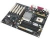
1.11.2 Thermal Monitoring Figure 13 shows the location of the sensors and fan connectors. Product Description 1 3 1 3 A B 1 C 3 D 3 1 G F E Item A B C D E F G Description Thermal diode, located on processor die Remote ambient temperature sensor Ambient temperature sensor, internal to hardware monitoring ASIC Processor fan Rear chassis fan Front chassis fan Voltage regulator fan Figure 13. Thermal Monitoring OM15884 39
-
 1
1 -
2
-
3
-
4
-
5
-
6
-
7
-
8
-
9
-
10
-
11
-
12
-
13
-
14
-
15
-
16
-
17
-
18
-
19
-
20
-
21
-
22
-
23
-
24
-
25
-
26
-
27
-
28
-
29
-
30
-
31
-
32
-
33
-
 34
34 -
 35
35 -
 36
36 -
 37
37 -
 38
38 -
 39
39 -
 40
40 -
 41
41 -
 42
42 -
 43
43 -
 44
44 -
45
-
46
-
47
-
48
-
49
-
50
-
51
-
52
-
53
-
54
-
55
-
56
-
57
-
58
-
59
-
60
-
61
-
62
-
63
-
64
-
65
-
66
-
67
-
68
-
69
-
70
-
71
-
72
-
73
-
74
-
75
-
76
-
77
-
78
-
79
-
80
-
81
-
82
-
83
-
84
-
85
-
86
-
87
-
88
-
89
-
90
-
91
-
92
-
93
-
94
-
95
-
96
-
97
-
98
-
99
-
100
-
101
-
102
-
103
-
104
-
105
-
106
-
107
-
108
-
109
-
110
-
111
-
112
-
113
-
114
-
115
-
116
-
117
-
118
-
119
-
120
-
121
-
122
-
123
-
124
-
125
-
126
-
127
-
128
-
129
-
130
-
131
-
132
 |
 |

Product Description
39
1.11.2
Thermal Monitoring
Figure 13 shows the location of the sensors and fan connectors.
OM15884
A
C
B
F
E
G
D
3
1
3
1
1
3
1
3
Item
Description
A
Thermal diode, located on processor die
B
Remote ambient temperature sensor
C
Ambient temperature sensor, internal to hardware monitoring ASIC
D
Processor fan
E
Rear chassis fan
F
Front chassis fan
G
Voltage regulator fan
Figure 13.
Thermal Monitoring