Intel KD875PBZLKPAK10 Product Specification - Page 8

s, Tables

Page 8 highlights

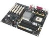
Intel Desktop Board D875PBZ Technical Product Specification Figures 1. Desktop Board D875PBZ Components 14 2. Block Diagram ...15 3. Memory Channel Configuration 23 4. Examples of Dual Channel configuration with Dynamic Mode 24 5. Example of Dual Channel configuration without Dynamic Mode 25 6. Examples of Single Channel configuration with Dynamic Mode 26 7. Examples of Single Channel configuration without Dynamic Mode 27 8. Intel 875P Chipset Block Diagram 28 9. Back Panel Audio Connector Options for Flex 6 Audio Subsystem 34 10. Adapter for S/PDIF Back Panel Connector 35 11. Flex 6 Audio Subsystem Block Diagram 35 12. LAN Connector LED Locations 37 13. Thermal Monitoring...39 14. Location of the Standby Power Indicator LED 46 15. Detailed System Memory Address Map 50 16. Back Panel Connectors 58 17. Audio Connectors ...61 18. Power and Hardware Control Connectors 63 19. D875PBZ Add-in Board and Peripheral Interface Connectors 66 20. External I/O Connectors 68 21. Connection Diagram for Front Panel Connector 69 22. Connection Diagram for Front Panel USB Connector 71 23. Location of the Jumper Blocks 72 24. Board Dimensions ...74 25. I/O Shield Dimensions for Boards with the Optional Audio Subsystem 75 26. I/O Shield Dimensions for Boards without the Audio Subsystem 76 27. Localized High Temperature Zones 80 Tables 1. Feature Summary...12 2. Manufacturing Options 13 3. Specifications ...17 4. Supported System Bus Frequency and Memory Speed Combinations 21 5. Supported Memory Configurations 22 6. Characteristics of Dual and Single Channel Configuration with and without Dynamic Mode ...23 7. LAN Connector LED States 38 8. Effects of Pressing the Power Switch 41 9. Power States and Targeted System Power 42 10. Wake-up Devices and Events 43 11. Fan Connector Function/Operation 44 12. System Memory Map 51 13. DMA Channels ...51 14. I/O Map ...52 15. PCI Configuration Space Map 53 viii

  • 1
  • 2
  • 3
  • 4
  • 5
  • 6
  • 7
  • 8
  • 9
  • 10
  • 11
  • 12
  • 13
  • 14
  • 15
  • 16
  • 17
  • 18
  • 19
  • 20
  • 21
  • 22
  • 23
  • 24
  • 25
  • 26
  • 27
  • 28
  • 29
  • 30
  • 31
  • 32
  • 33
  • 34
  • 35
  • 36
  • 37
  • 38
  • 39
  • 40
  • 41
  • 42
  • 43
  • 44
  • 45
  • 46
  • 47
  • 48
  • 49
  • 50
  • 51
  • 52
  • 53
  • 54
  • 55
  • 56
  • 57
  • 58
  • 59
  • 60
  • 61
  • 62
  • 63
  • 64
  • 65
  • 66
  • 67
  • 68
  • 69
  • 70
  • 71
  • 72
  • 73
  • 74
  • 75
  • 76
  • 77
  • 78
  • 79
  • 80
  • 81
  • 82
  • 83
  • 84
  • 85
  • 86
  • 87
  • 88
  • 89
  • 90
  • 91
  • 92
  • 93
  • 94
  • 95
  • 96
  • 97
  • 98
  • 99
  • 100
  • 101
  • 102
  • 103
  • 104
  • 105
  • 106
  • 107
  • 108
  • 109
  • 110
  • 111
  • 112
  • 113
  • 114
  • 115
  • 116
  • 117
  • 118
  • 119
  • 120
  • 121
  • 122
  • 123
  • 124
  • 125
  • 126
  • 127
  • 128
  • 129
  • 130
  • 131
  • 132

Intel Desktop Board D875PBZ Technical Product Specification
viii
Figures
1.
Desktop Board D875PBZ Components
......................................................................
14
2.
Block Diagram
............................................................................................................
15
3.
Memory Channel Configuration
..................................................................................
23
4.
Examples of Dual Channel configuration with Dynamic Mode
....................................
24
5.
Example of Dual Channel configuration without Dynamic Mode
.................................
25
6.
Examples of Single Channel configuration with Dynamic Mode
..................................
26
7.
Examples of Single Channel configuration without Dynamic Mode
.............................
27
8.
Intel 875P Chipset Block Diagram
..............................................................................
28
9.
Back Panel Audio Connector Options for Flex 6 Audio Subsystem
............................
34
10.
Adapter for S/PDIF Back Panel Connector
.................................................................
35
11.
Flex 6 Audio Subsystem Block Diagram
.....................................................................
35
12.
LAN Connector LED Locations
...................................................................................
37
13.
Thermal Monitoring
.....................................................................................................
39
14.
Location of the Standby Power Indicator LED
............................................................
46
15.
Detailed System Memory Address Map
......................................................................
50
16.
Back Panel Connectors
..............................................................................................
58
17.
Audio Connectors
.......................................................................................................
61
18.
Power and Hardware Control Connectors
..................................................................
63
19.
D875PBZ Add-in Board and Peripheral Interface Connectors
....................................
66
20.
External I/O Connectors
.............................................................................................
68
21.
Connection Diagram for Front Panel Connector
.........................................................
69
22.
Connection Diagram for Front Panel USB Connector
.................................................
71
23.
Location of the Jumper Blocks
....................................................................................
72
24.
Board Dimensions
......................................................................................................
74
25.
I/O Shield Dimensions for Boards with the Optional Audio Subsystem
.......................
75
26.
I/O Shield Dimensions for Boards without the Audio Subsystem
................................
76
27.
Localized High Temperature Zones
............................................................................
80
Tables
1.
Feature Summary
.......................................................................................................
12
2.
Manufacturing Options
...............................................................................................
13
3.
Specifications
.............................................................................................................
17
4.
Supported System Bus Frequency and Memory Speed Combinations
.......................
21
5.
Supported Memory Configurations
.............................................................................
22
6.
Characteristics of Dual and Single Channel Configuration with and without
Dynamic Mode
...........................................................................................................
23
7.
LAN Connector LED States
........................................................................................
38
8.
Effects of Pressing the Power Switch
.........................................................................
41
9.
Power States and Targeted System Power
................................................................
42
10.
Wake-up Devices and Events
.....................................................................................
43
11.
Fan Connector Function/Operation
.............................................................................
44
12.
System Memory Map
..................................................................................................
51
13.
DMA Channels
...........................................................................................................
51
14.
I/O Map
......................................................................................................................
52
15.
PCI Configuration Space Map
....................................................................................
53