Intel S845WD1-E Product Guide
Intel S845WD1-E - Server Board Motherboard Manual
 |
UPC - 735858159272
View all Intel S845WD1-E manuals
Add to My Manuals
Save this manual to your list of manuals |
Intel S845WD1-E manual content summary:
- Intel S845WD1-E | Product Guide - Page 1
Intel® Server Board S845WD1-E (S845WD1H) Product Guide A Guide for Technically Qualified Assemblers of Intel® Identified Subassemblies/Products Order Number: C22229-001 - Intel S845WD1-E | Product Guide - Page 2
that all other technology used in combination with said product properly exchanges date data with it. Intel, Pentium, LANDesk and Celeron are the trademarks or registered trademarks of Intel Corporation or its subsidiaries in the United States and other countries. † Other names and brands may be - Intel S845WD1-E | Product Guide - Page 3
IDE Support ...20 BIOS Updates...21 Language Support 21 Custom Splash Screen 21 Recovering BIOS Data 22 Boot Options...22 CD-ROM and Network Boot 22 Booting Without Attached Devices 23 Fast Booting Systems with Intel® Rapid BIOS Boot 23 Intel Rapid BIOS Boot 23 BIOS Security Passwords - Intel S845WD1-E | Product Guide - Page 4
the Intel® Express BIOS Update Utility 51 Updating the BIOS with the Intel® Flash Memory Update Utility 51 Preparing for the Update 51 Obtaining the BIOS Update File 52 Recording the Current BIOS Settings 52 Creating Bootable Media 52 iv Intel Server Board S845WD1-E (S845WD1H) Product Guide - Intel S845WD1-E | Product Guide - Page 5
73 Hard Disk Drives Submenu 74 Removable Devices Submenu 74 ATAPI CDROM Drives Submenu 75 Exit Menu ...75 4 Solving BIOS Problems 77 BIOS Beep Codes ...77 BIOS Error Messages...78 5 Getting Help 81 World Wide Web ...81 Telephone ...81 6 Technical Reference 83 Server Board Connectors 83 - Intel S845WD1-E | Product Guide - Page 6
12. Table 13. Server Board Features 9 Supported Processors 13 Supported Memory Configurations 13 Supervisor and User Password Functions 24 Effects of Pressing the Power the BIOS Setup Program Modes 50 BIOS Setup Program Menu Bar 56 vi Intel Server Board S845WD1-E (S845WD1H) Product Guide - Intel S845WD1-E | Product Guide - Page 7
Boot Device Priority Submenu 73 Hard Disk Drives Submenu 74 Removable Devices Submenu 74 ATAPI CDROM Drives Submenu 75 Exit Menu ...75 Beep Codes 77 BIOS Error Messages 78 System Memory Map 86 DMA Channels 86 I/O Map ...87 Interrupts ...88 Product Certification Markings 92 Contents vii - Intel S845WD1-E | Product Guide - Page 8
viii Intel Server Board S845WD1-E (S845WD1H) Product Guide - Intel S845WD1-E | Product Guide - Page 9
Server Board Features Feature Processors Description Support for an Intel® Pentium® 4 processor in a µPGA478 socket Support for an Intel® Celeron® processor in a µPGA478 socket 400/533 MHz Supported Memory • Two 184-pin DDR SDRAM Dual Inline Memory Module (DIMM) sockets • Support for up to 2 GB - Intel S845WD1-E | Product Guide - Page 10
99 recommendations. A C F B D E GH I A. PS/2 mouse B. PS/2 keyboard C. Parallel port D. Serial port A E. Video port F. NIC 1 G. USB port 1 H. USB port 2 I. NIC 2 Figure 1. Back Panel Connectors OM14342 10 Intel Server Board S845WD1-E (S845WD1H) Product Guide - Intel S845WD1-E | Product Guide - Page 11
Front Panel Connectors Figure 2 shows the location of the front panel connectors. A B A. Front panel header B. HDD LED Figure 2. Front Panel Connectors TP00011 Description 11 - Intel S845WD1-E | Product Guide - Page 12
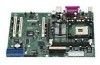
auxiliary power connector V. Front panel header H. µPGA478 processor socket W. System fan (fan 1) I. Intel 82845E memory controller hub (MCH) X. Secondary RAID IDE connector Secondary IDE connector Figure 3. Server Board Components 12 Intel Server Board S845WD1-E (S845WD1H) Product Guide - Intel S845WD1-E | Product Guide - Page 13
Processors The S845WD1H board supports a single Intel Pentium 4 processor with a µPGA478 socket. Processors are not included with the server board and must be purchased separately. Table 2. Supported Processors Type Designation Pentium 4 processor with 3.06 GHz Hyperthreading (HT) Technology - Intel S845WD1-E | Product Guide - Page 14
bus ECC can be disabled or enabled by BIOS. It is enabled by default. The MCH provides the following: • An integrated Synchronous DRAM memory controller with auto detection of SDRAM. • Support for ACPI Rev 1.0b compliant power management. 14 Intel Server Board S845WD1-E (S845WD1H) Product Guide - Intel S845WD1-E | Product Guide - Page 15
82801BA I/O Controller Hub (ICH2) The Intel 82801BA ICH2 has these features: • 33 MHz Peripheral Component Interface (PCI) Local Bus slots supporting PCI specification, Rev 2.2. • Support for the Low Pin Count (LPC) interface. • Integrated IDE controller (supports Ultra ATA-66/100 mode and Ultra - Intel S845WD1-E | Product Guide - Page 16
supports data transfers at speeds up to 115.2 kb/s with BIOS support. specification. The board has several hardware management features, including the following: • Fan monitoring • Thermal and voltage monitoring • Chassis intrusion detection 16 Intel Server Board S845WD1-E (S845WD1H) Product Guide - Intel S845WD1-E | Product Guide - Page 17
of processor Intel® LANDesk® Client Manager or third-party software. Chassis Intrusion and Detection The S845WD1H server board supports supports 256 bytes of battery-backed CMOS SRAM in two banks that are reserved for BIOS use. A coin-cell battery (CR2032) powers the real-time clock and CMOS memory - Intel S845WD1-E | Product Guide - Page 18
Legacy USB support in the BIOS Setup program is set to Enabled and follow the operating system's installation instructions. ✏ NOTE Legacy USB support is for keyboard, mice, and hubs only. Other USB devices are not supported in legacy mode. 18 Intel Server Board S845WD1-E (S845WD1H) Product Guide - Intel S845WD1-E | Product Guide - Page 19
support the following modes: • Programmed I/O (PIO): processor controls data transfer. • 8237-style DMA: DMA offloads the processor, supporting reports the transfer rate and translation mode to the BIOS. The S845WD1H server board supports Laser Servo (LS-120) diskette technology through the - Intel S845WD1-E | Product Guide - Page 20
support. The S845WD1H server board supports system BIOS shadowing, allowing the BIOS to execute from 64-bit onboard write-protected system memory. The BIOS displays a message during POST identifying the type of BIOS of the slowest device. 20 Intel Server Board S845WD1-E (S845WD1H) Product Guide - Intel S845WD1-E | Product Guide - Page 21
updating while in the Windows environment. Using this utility, the BIOS can be updated from a file on a hard disk, a 1.44 MB diskette, or a CD-ROM, or from the file location on the Web. • Intel® Flash Memory Update Utility, which requires creation of a boot diskette and manual rebooting of the - Intel S845WD1-E | Product Guide - Page 22
CD in the CD-ROM drive, the system will attempt to boot from the next defined drive. The network can be selected as a boot device. This selection allows booting from the on-board NIC or a network add-in card with a remote boot ROM installed. 22 Intel Server Board S845WD1-E (S845WD1H) Product Guide - Intel S845WD1-E | Product Guide - Page 23
devices are not present: • Video adapter • Keyboard • Mouse Fast Booting Systems with Intel® Rapid BIOS Boot These factors affect system boot complex graphic images and changing video modes. • Enabled Intel® Rapid BIOS Boot. This feature bypasses memory count and the search for a diskette drive. ✏ - Intel S845WD1-E | Product Guide - Page 24
options limited number Enter Password of options Note: If no password is set, any user can change all Setup options. Password to Enter Setup None Supervisor User Supervisor or user Password During Boot None None User Supervisor or user 24 Intel Server Board S845WD1-E (S845WD1H) Product Guide - Intel S845WD1-E | Product Guide - Page 25
• Resource data, such as memory size, cache size, and processor speed • Dynamic data, such as event detection and error logging Non-Plug and Play operating systems, such as Windows NT†, require an additional interface for obtaining the SMBIOS information. The BIOS supports an SMBIOS table interface - Intel S845WD1-E | Product Guide - Page 26
Wake on LAN Technology Network adapters that are PCI 2.2 in memory, etc. Wake on Ring The operation of Wake on Ring can be summarized as follows: • Powers up the server from the ACPI S5 state. • Modem must support PME. for correct operation. 26 Intel Server Board S845WD1-E (S845WD1H) Product Guide - Intel S845WD1-E | Product Guide - Page 27
with the S845WD1H server board requires an operating system that provides full ACPI support. ACPI features include: • Plug and Play (including bus and device enumeration) • Power management control of individual devices, add-in boards (some add-in boards may require an ACPI-aware driver - Intel S845WD1-E | Product Guide - Page 28
the power states supported by the S845WD1H board along with the associated system power targets. See the ACPI specification for a complete description of the various system and power states. Table 6. Power States and Targeted System Power Global States Sleeping States Processor States Device - Intel S845WD1-E | Product Guide - Page 29
specific events that can wake the computer from specific states an OS that supports this wake event. 2. For LAN and PME#, S5 is disabled by default in the BIOS Setup program. support. In addition, software, drivers, and peripherals must fully support ACPI wake events. Hardware Support The S845WD1H - Intel S845WD1-E | Product Guide - Page 30
BIOS Setup program's Boot menu. ✏ NOTE A standard ATX 20 pin power connector and standard ATX 12V 4 pin 2x2 connector can be used to power the S845WD1H board. Plug the power cables into the pin 1 end of their respective motherboard ASIC. 30 Intel Server Board S845WD1-E (S845WD1H) Product Guide - Intel S845WD1-E | Product Guide - Page 31
subsystem PCI bus network adapter monitors network traffic at the Media Independent Interface. Upon detecting a Magic Packet† frame, the LAN subsystem asserts a wake-up signal that powers up the computer. Depending on the LAN implementation, the S845WD1H server board supports LAN wake capabilities - Intel S845WD1-E | Product Guide - Page 32
from PS/2 Devices PS/2 device activity wakes the computer from an ACPI S1 state. PME# Wake-up Support When the PME# signal on the PCI bus is asserted, the computer wakes from an ACPI S1, S4, or S5 state (with Wake on PME enabled in BIOS). 32 Intel Server Board S845WD1-E (S845WD1H) Product Guide - Intel S845WD1-E | Product Guide - Page 33
Local Bus Specification, Rev 2.2. The PCI bus is directed through the Intel 82801BA I/O Controller Hub (ICH2). The table below lists the characteristics of the PCI bus. Table 9. Voltage 5 V PCI Bus Characteristics Width Speed 32-bits 33 MHz Type Independent Bus Comments Supports full-length - Intel S845WD1-E | Product Guide - Page 34
host interface complies with PCI Local Bus Specification Revision 2.2. • 32-bit, 33-MHz bus speed and 132 MB/sec sustained transfer rate. The Promise PDC20267 supports IDE RAID through dual ATA-100 for storage capacity and data redundancy. 34 Intel Server Board S845WD1-E (S845WD1H) Product Guide - Intel S845WD1-E | Product Guide - Page 35
SDRAM chip provides 8 MB of video memory. The SVGA subsystem supports a variety of modes, up to 1600 supports both CRT and LCD monitors up to 100 Hz vertical refresh rate. The S845WD1H server board provides a standard 15-pin VGA connector and supports disabling of the on-board video through the BIOS - Intel S845WD1-E | Product Guide - Page 36
user guides that provide more information on using Intel LDCM software are available on the Intel Server Board S845WD1H Resource CD and are also available for download at: http://www.support.intel.com/support/motherboards/server/S845WD1-E 36 Intel Server Board S845WD1-E (S845WD1H) Product Guide - Intel S845WD1-E | Product Guide - Page 37
EMC compliance testing. For more information please contact your local Intel Representative. See "Regulatory and Integration Information" on page 91 Turn off the server and disconnect the power cord, telecommunications systems, networks, and modems attached to the server before opening it. Otherwise, - Intel S845WD1-E | Product Guide - Page 38
for the latest tested memory list: http://support.intel.com/support/motherboards/server/S845WD1-E DIMM Installation Guidelines All memory components and DIMMs used with the S845WD1-# server board must comply with the DDR specifications. These include the following: • Intel® Spec Addendum Rev 0.9 for - Intel S845WD1-E | Product Guide - Page 39
Installing DIMMs To install DIMMs, follow these steps: 1. Observe the safety and ESD precautions at the beginning of this chapter. 2. Turn off all peripheral devices connected to the server. Turn off the server and disconnect the AC power cord. 3. Remove the server's cover and locate the DIMM - Intel S845WD1-E | Product Guide - Page 40
. 7. Reinstall and reconnect any parts you removed or disconnected to reach the DIMM sockets. 8. Replace the server's cover and reconnect the AC power cord. 40 Intel Server Board S845WD1-E (S845WD1H) Product Guide - Intel S845WD1-E | Product Guide - Page 41
Installing the I/O Shield CAUTION Systems based on the S845WD1H server board need the I/O shield properly installed to pass emissions (EMI) certification testing and to meet Class B emissions compliance levels. Without the I/O shield, or with - Intel S845WD1-E | Product Guide - Page 42
Installing the Server Board Refer to your chassis manual for instructions on installing the server board. Eight screws secure the server board to the chassis. or equipment damage. Figure 7. Location of the Mounting Screw Holes TP00004 42 Intel Server Board S845WD1-E (S845WD1H) Product Guide - Intel S845WD1-E | Product Guide - Page 43
To install a processor, follow these instructions: 1. Observe the safety and ESD precautions at the beginning of this chapter. 2. Locate the processor socket and raise the socket handle completely (see Figure 8, B). 3. Aligning the pins of the processor with the socket, insert the processor into the - Intel S845WD1-E | Product Guide - Page 44
the heat sink and clip assembly with the retention mechanism and place it on the processor. The heat sink is symmetrical. b. With the clip levers in the up position, OM14470 Figure 10. Attaching the Fan Heat Sink Clips to the Processor Socket 44 Intel Server Board S845WD1-E (S845WD1H) Product Guide - Intel S845WD1-E | Product Guide - Page 45
A OM14483 Figure 11. Connecting the Processor Fan Cable to the Processor Fan Connector Removing the Processor To remove the processor, follow these instructions: 1. Observe the safety and ESD precautions at the beginning of this chapter. 2. Disconnect the processor fan cable. 3. Detach the fan heat - Intel S845WD1-E | Product Guide - Page 46
lose voltage. When the voltage drops below a certain level, the BIOS Setup program settings stored in CMOS RAM (for example, the date si la pile usagée est remplacée par une pile de type incorrect. Les piles usagées doivent être recyclées dans 46 Intel Server Board S845WD1-E (S845WD1H) Product Guide - Intel S845WD1-E | Product Guide - Page 47
igualmente las instrucciones del fabricante. (Spanish) WAARSCHUWING Er bestaat ontploffingsgevaar als de batterij wordt vervangen door een onjuist type batterij. Batterijen moeten zoveel mogelijk worden gerecycled. Houd u bij het weggooien van gebruikte batterijen aan de plaatselijke milieuwetgeving - Intel S845WD1-E | Product Guide - Page 48
the server. Disconnect the server's power cord from the AC power source (wall outlet or power adapter). 3. Remove the server cover. 4. Locate the battery on the board (see Figure 12). server cover. Figure 12. Removing the Battery TP00005 48 Intel Server Board S845WD1-E (S845WD1H) Product Guide - Intel S845WD1-E | Product Guide - Page 49
Connecting the IDE Cable The Intel® boxed server board package includes a 40-contact, 80-conductor IDE cable. It is capable of connecting two drives to the server board. The cable supports Ultra ATA/66 and Ultra ATA/100 transfer protocols and is backward compatible with drives using slower IDE - Intel S845WD1-E | Product Guide - Page 50
and passwords for booting. 1 Configure 3 2-3 After the POST runs, Setup runs automatically. The maintenance menu is displayed. 1 Recovery 3 None The BIOS attempts to recover the BIOS configuration. A recovery diskette is required. 1 50 Intel Server Board S845WD1-E (S845WD1H) Product Guide - Intel S845WD1-E | Product Guide - Page 51
of the Intel Flash Memory Update Utility and the ease-of use of Windows-based installation wizards. To update the BIOS with the Intel Express BIOS Update utility: 1. Go to the Intel support web site: http://support.intel.com/support/motherboards/server 2. Navigate to the S845WD1H page and - Intel S845WD1-E | Product Guide - Page 52
BIOS. The BIOS update file contains: • New BIOS files • BIOS recovery files • Intel Flash Memory Update Utility You can obtain the BIOS update file through your server supplier or from the Intel World Wide Web site: http://support.intel.com/support/motherboards/server/ ✏ NOTE Review the instructions - Intel S845WD1-E | Product Guide - Page 53
or from the Intel World Wide Web site: http://support.intel.com/support/motherboards/server/ 2. Copy the BIOS update file to a temporary directory on your hard disk. 3. From the C:\ prompt, change to the temporary directory. 4. To extract the file, type the name of the BIOS upgrade file, for - Intel S845WD1-E | Product Guide - Page 54
completed successfully message and second, updating the BIOS core. You will be asked to reboot the system BIOS upgrade. 9. To save the settings, press . 10. To accept the settings, press . 11. Turn off the server and reboot. 54 Intel Server Board S845WD1-E (S845WD1H) Product Guide - Intel S845WD1-E | Product Guide - Page 55
BIOS if an update fails. The following procedure uses recovery mode for the Setup program. See page 50 for more information on Setup modes. ✏ NOTE Because of the small amount of code available in the boot block area, there is no video support successful recovery of the BIOS core. Drive A activity - Intel S845WD1-E | Product Guide - Page 56
management features Selects boot options and power supply controls Saves or discards changes to Setup program options * For information about the BIS, refer to the Intel Web site at: http://developer.intel.com/design/security/index1.htm 56 Intel Server Board S845WD1-E (S845WD1H) Product Guide - Intel S845WD1-E | Product Guide - Page 57
and exits the BIOS Setup program. to access processor information. User-Defined CPU Information No options CPU Microcode Update Revision No options CPU Stepping Signature No options Description Clears the user and administrative passwords. Clears the Wired for Management Boot Integrity Service - Intel S845WD1-E | Product Guide - Page 58
driver and the application must support Write-Combining. • UC (default) Selects UnCacheable (UC) video memory cache mode. This setting identifies the video memory range as uncacheable by the processor. Memory . • 6 • 5 • Auto (default) 58 Intel Server Board S845WD1-E (S845WD1H) Product Guide - Intel S845WD1-E | Product Guide - Page 59
If non-ECC memory is installed, BIOS will detect and change the setting to nonECC. Specifies the current time. Specifies the current date. ✏ NOTE Additional language support available. For more information visit Intel's support web site at: www.support.intel.com/support/motherboards/server/S845WD1 - Intel S845WD1-E | Product Guide - Page 60
If Used is displayed, User-Defined has been selected in type of connected IDE device. When selected, displays the Diskette Configuration submenu. Configures Event Logging. When selected, displays the Event Log Configuration submenu. 60 Intel Server Board S845WD1-E (S845WD1H) Product Guide - Intel S845WD1-E | Product Guide - Page 61
PCI Configuration Submenu To access this submenu, select Advanced on the menu bar, then PCI Configuration. Maintenance Main Advanced Security Power PCI Configuration Boot Configuration Peripheral Configuration IDE Configuration Diskette Configuration Event Log Configuration Boot Exit The - Intel S845WD1-E | Product Guide - Page 62
in flash memory on the next boot. Yes clears the PCI/PnP configuration data stored in flash memory on the next boot. Numlock • Off • On (default) Specifies the power-on state of the Numlock feature on the numeric keypad of the keyboard. 62 Intel Server Board S845WD1-E (S845WD1H) Product Guide - Intel S845WD1-E | Product Guide - Page 63
Peripheral Configuration Submenu To access this submenu, select Advanced on the menu bar, then Peripheral Configuration. Maintenance Main Advanced Security Power PCI Configuration Boot Configuration Peripheral Configuration IDE Configuration Diskette Configuration Event Log Configuration Boot - Intel S845WD1-E | Product Guide - Page 64
RAID controller. • Enabled (default) ATI Rage Video • Disabled • Enabled (default) Enables or disables the on-board ATI* Rage video controller. Legacy USB Support • Disabled Enables or disables Legacy USB support. • Enabled (default) 64 Intel Server Board S845WD1-E (S845WD1H) Product Guide - Intel S845WD1-E | Product Guide - Page 65
-delay. • 3 Seconds • 6 Seconds • 9 Seconds • 12 Seconds • 15 Seconds • 21 Seconds • 30 Seconds Primary IDE Master Select to display sub-menu Reports type of connected IDE device. When selected, displays the Primary IDE Master submenu. Primary IDE Slave Select to display sub-menu Reports - Intel S845WD1-E | Product Guide - Page 66
Description Drive Installed No options Displays the type of drive installed. Type • None • User • Auto (default) • CD-ROM the hard disk drive to memory. Check the hard disk drive's specifications for optimum setting. continued 66 Intel Server Board S845WD1-E (S845WD1H) Product Guide - Intel S845WD1-E | Product Guide - Page 67
• Mode 1 • Mode 2 • Mode 3 • Mode 4 • Mode 5 No options Description Specifies the PIO mode. Specifies the Ultra DMA mode for the drive. Displays the type of cable connected to the IDE interface: 40-conductor or 80-conductor (for ATA-66/100 devices). Note: These configuration options appear only if - Intel S845WD1-E | Product Guide - Page 68
(default) ECC Event Logging • Disabled Enables logging of ECC events. • Enabled (default) Mark Events As Read • Yes (default) Marks all events as read. • No 68 Intel Server Board S845WD1-E (S845WD1H) Product Guide - Intel S845WD1-E | Product Guide - Page 69
used to configure the video features. Table 26. Video Configuration Submenu Feature Options AGP Aperture Size • 64MB (default) • 256MB Primary Video Adapter • AGP (default) • PCI Description Sets the aperture size for the AGP video controller. Allows selecting an AGP or PCI video controller - Intel S845WD1-E | Product Guide - Page 70
the user to enter a password. 4. When Unattended Start is enabled, a USB aware operating system may override user password protection if used in conjunction with a USB keyboard and mouse without requiring the user to enter a password. 70 Intel Server Board S845WD1-E (S845WD1H) Product Guide - Intel S845WD1-E | Product Guide - Page 71
Power Menu To access this menu, select Power from the menu bar at the top of the screen. Maintenance Main Advanced Security Power ACPI Boot Exit The menu represented in Table 28 is for setting the power management features. Table 28. Power Menu Feature Options ACPI No Options After - Intel S845WD1-E | Product Guide - Page 72
from the available types of boot devices. Specifies the boot sequence from the available hard disk drives. Specifies the boot sequence from the available removable devices. Specifies the boot sequence from the available ATAPI CD-ROM drives. 72 Intel Server Board S845WD1-E (S845WD1H) Product Guide - Intel S845WD1-E | Product Guide - Page 73
2nd Boot Device 3rd Boot Device 4th Boot Device (Note 1) • Removable Dev. • Hard Drive • ATAPI CD-ROM • Intel® UNDI, PXE • Disabled Specifies the boot sequence from the available types of boot devices. To specify boot sequence: 1. Select the boot device with or . 2. Press to set - Intel S845WD1-E | Product Guide - Page 74
intended boot device. Note: This boot device submenu appears only if at least one boot device of this type is installed. This list will display up to four removable devices, the maximum number of removable devices supported by the BIOS. 74 Intel Server Board S845WD1-E (S845WD1H) Product Guide - Intel S845WD1-E | Product Guide - Page 75
this type is installed. This list will display up to four ATAPI CDROM drives, the maximum number of ATAPI CDROM drives supported by the BIOS. Exit BIOS reads the Setup values from flash memory. If this memory is corrupted, the BIOS reads the custom defaults. If no custom defaults are set, the BIOS - Intel S845WD1-E | Product Guide - Page 76
76 Intel Server Board S845WD1-E (S845WD1H) Product Guide - Intel S845WD1-E | Product Guide - Page 77
4 Timer not operational 5 Processor failure (Reserved; not used) 6 8042 GateA20 cannot be toggled (memory failure or not present) 7 Exception interrupt error 8 Display memory R/W error 9 (Reserved; not used) 10 CMOS Shutdown register test error 11 Invalid BIOS (such as, POST module - Intel S845WD1-E | Product Guide - Page 78
to be updated. Keyboard Error Error in the keyboard connection. Make sure keyboard is connected properly. KB/Interface Error Keyboard interface test failed. continued 78 Intel Server Board S845WD1-E (S845WD1H) Product Guide - Intel S845WD1-E | Product Guide - Page 79
in onboard memory at an unknown address. NVRAM / CMOS / PASSWORD cleared by Jumper NVRAM, CMOS, and passwords have been cleared. The system should be powered down and the jumper removed. Pressed CMOS is ignored and NVRAM is cleared. User must enter Setup. Solving BIOS Problems 79 - Intel S845WD1-E | Product Guide - Page 80
80 Intel Server Board S845WD1-E (S845WD1H) Product Guide - Intel S845WD1-E | Product Guide - Page 81
World Wide Web http://support.intel.com/support/motherboards/server/S845WD1-E Telephone Talk to a Customer Support Technician.* All calls are billed US $25.00 per incident, levied in local currency at the applicable credit card exchange rate plus applicable taxes. (Intel reserves the right to - Intel S845WD1-E | Product Guide - Page 82
82 Intel Server Board S845WD1-E (S845WD1H) Product Guide - Intel S845WD1-E | Product Guide - Page 83
cable, and the external devices themselves. ✏ NOTE A standard ATX 20 pin power connector and standard ATX 12V 4 pin 2x2 connector can be used to power the S845WD1H board. Plug the power cables into the pin 1 end of their respective motherboard connectors, leaving pins 21-24 unused on the main power - Intel S845WD1-E | Product Guide - Page 84
Figure 15 shows the power and hardware connectors. 51 84 A 1 B C 1 1 1 24 13 12 1 F E D A. Chassis fan B. Aux power C. Processor fan D. Power E. Chassis fan F. Chassis fan Figure 15. Power and Hardware Control Connectors TP00008 84 Intel Server Board S845WD1-E (S845WD1H) Product Guide - Intel S845WD1-E | Product Guide - Page 85
Add-In Board and Peripheral Interface Connectors Figure 16 shows the add-in board and peripheral interface connectors. AB C 40 2 1 39 2 40 1 39 2 34 1 33 F E D A. PCI slot 3 B. PCI slot 2 C. PCI slot 1 D. Diskette drive E. Primary IDE F. Secondary IDE Figure 16. Add-in Board and - Intel S845WD1-E | Product Guide - Page 86
memory Runtime BIOS Reserved Available high DOS memory (open to the PCI bus) Video memory and BIOS Extended BIOS data (movable by memory manager software) Extended conventional memory Conventional memory (for ECP or EPP) & COM2 Open Open Open 86 Intel Server Board S845WD1-E (S845WD1H) Product Guide - Intel S845WD1-E | Product Guide - Page 87
DMA controller Fast A20 and PIC PIC APM control DMA Numeric data processor Secondary IDE channel Primary IDE channel LPT3 LPT2 COM4/video (8514A) IDE channel command port Secondary IDE channel status port LPT1 Intel 82845 MCH Intel 82845 MCH COM3 Diskette channel 1 Diskette channel 2 Primary IDE - Intel S845WD1-E | Product Guide - Page 88
(APIC) portion of the ICH2 component. The APIC is supported in Windows† 2000 Server and Windows XP and supports a total of twenty-four interrupts. Table 41. IRQ NMI for ICH2 system management bus User available User available continued 88 Intel Server Board S845WD1-E (S845WD1H) Product Guide - Intel S845WD1-E | Product Guide - Page 89
) (optional) (through PIRQC) ICH2 USB controller 1 (through PIRQD) On-board ATI Rage XL PCI (optional)/User available (through PIRQF) (optional)/User available (through PIRQG) ICH2 USB controller 2/User available (through PIRQH) Notes: 1. Default, but can be changed to another IRQ. 2. Available in - Intel S845WD1-E | Product Guide - Page 90
90 Intel Server Board S845WD1-E (S845WD1H) Product Guide - Intel S845WD1-E | Product Guide - Page 91
Nordics) • GOST R 50377-92 (Russia) Product EMC Compliance The S845WD1H has been has been tested and verified to comply with the following information on compatible host system(s) refer to Intel's Server Builder website or contact your local Intel representative. • FCC (Class A Verification - Intel S845WD1-E | Product Guide - Page 92
any interference received, including interference that may cause undesired operation. For questions related to the EMC performance of this product, contact: Intel Corporation 5200 N.E. Elam Young Parkway Hillsboro, OR 97124 1-800-628-8686 92 Intel Server Board S845WD1-E (S845WD1H) Product Guide - Intel S845WD1-E | Product Guide - Page 93
energy and, if not installed and used in accordance with the instructions, may cause harmful interference to radio communications. However, there is reception, which can be determined by turning the equipment off and on, the user is encouraged to try to correct the interference by one or more of the - Intel S845WD1-E | Product Guide - Page 94
• Hot components (like processors, voltage regulators, and heat sinks) • Damage to wires that could cause a short circuit Observe all warnings and cautions that instruct you to refer computer servicing to qualified technical personnel. 94 Intel Server Board S845WD1-E (S845WD1H) Product Guide - Intel S845WD1-E | Product Guide - Page 95
and adhere to all of these instructions and the instructions supplied with the chassis and associated modules. If the instructions for the chassis are inconsistent with these instructions or the instructions for associated modules, contact the supplier's technical support to find out how you can - Intel S845WD1-E | Product Guide - Page 96
96 Intel Server Board S845WD1-E (S845WD1H) Product Guide
-
 1
1 -
 2
2 -
 3
3 -
 4
4 -
 5
5 -
 6
6 -
 7
7 -
8
-
9
-
10
-
11
-
12
-
13
-
14
-
15
-
16
-
17
-
18
-
19
-
20
-
21
-
22
-
23
-
24
-
25
-
26
-
27
-
28
-
29
-
30
-
31
-
32
-
33
-
34
-
35
-
36
-
37
-
38
-
39
-
40
-
41
-
42
-
43
-
44
-
45
-
46
-
47
-
48
-
49
-
50
-
51
-
52
-
53
-
54
-
55
-
56
-
57
-
58
-
59
-
60
-
61
-
62
-
63
-
64
-
65
-
66
-
67
-
68
-
69
-
70
-
71
-
72
-
73
-
74
-
75
-
76
-
77
-
78
-
79
-
80
-
81
-
82
-
83
-
84
-
85
-
86
-
87
-
88
-
89
-
90
-
91
-
92
-
93
-
94
-
95
-
96
 |
 |

Intel
®
Server Board S845WD1-E
(S845WD1H) Product Guide
A Guide for Technically Qualified Assemblers of Intel
®
Identified
Subassemblies/Products
Order Number:
C22229-001