Invacare M91R Owners Manual
Invacare M91R Manual
 |
View all Invacare M91R manuals
Add to My Manuals
Save this manual to your list of manuals |
Invacare M91R manual content summary:
- Invacare M91R | Owners Manual - Page 1
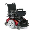
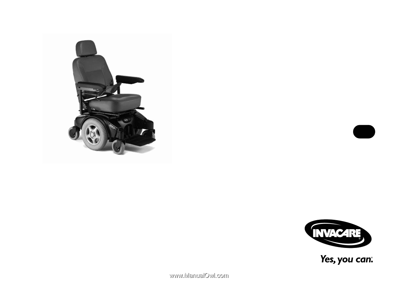
Invacare® Pronto® M91™ Power Wheelchair Base with SureStep® User Manual EN This manual MUST be given to the user of the product. BEFORE using this product, read this manual and save for future reference. - Invacare M91R | Owners Manual - Page 2
duplication or modification in whole or in part is prohibited without prior written permission from Invacare. Trademarks are identified by ™ and ®. All trademarks are owned by or licensed to Invacare Corporation or its subsidiaries unless otherwise noted. Invacare® Pronto® M91™ 2 Part No 1143153 - Invacare M91R | Owners Manual - Page 3
...13 2 SAFETY 15 General Guidelines ...15 Operation Information ...16 Setup ...16 Accessories Information...16 Powered Seating Systems Only ...16 Transport...17 Repair or Service Information ...19 Safety/Handling ...20 A Note to Wheelchair Assistants...21 Stability and Balance ...22 Coping - Invacare M91R | Owners Manual - Page 4
Reaching, Bending - Backward ...28 Transferring To and From Other Seats...29 Storage...30 Electrical - Grounding Instructions...31 Electrical - Batteries ...31 Electrical - Charging Batteries...32 On/Off...41 Using the Joystick to Drive the Wheelchair...42 Invacare® Pronto® M91™ 4 Part No 1143153 - Invacare M91R | Owners Manual - Page 5
Speed Control Buttons...45 Joystick ...46 Charger/Programming Input...46 Information Gauge Display ...46 Service Indicator ...46 CMPJ+ Joystick Switches and Indicators...47 On/Off - Drive Select Toggle Battery Charger...59 Independent Battery Charger ...61 Part No 1143153 5 Invacare® Pronto® M91™ - Invacare M91R | Owners Manual - Page 6
Removing ...62 Installing...62 Tilting the Seat Assembly ...64 Tilting the Seat Assembly Back ...64 Tilting the Seat Assembly Forward...65 6 MOTOR LOCKS 66 ...72 Wheelchair-Anchored Belts...72 Vehicle-Anchored Belts...74 Seating System ...74 Positioning Belts ...75 8 SETUP/MAINTENANCE 77 - Invacare M91R | Owners Manual - Page 7
CONTENTS Service Inspection ...80 Six Month Inspection ...80 Inspect/Adjust Every 18 Months...82 Batteries ...83 Using the Front/Rear Caster Assemblies...100 Adjusting Forks ...101 Repositioning Joystick ...102 Adjustable ASBA ...102 Van Seat...103 Part No 1143153 7 Invacare® Pronto® M91™ - Invacare M91R | Owners Manual - Page 8
...104 SPJ+ Joysticks ...104 MPJ+ Joysticks...105 9 TROUBLESHOOTING 106 Driving Performance ...106 Electrical ...106 SPJ+, SPJ+ w/PSS or SPJ+ w/ACC Joysticks...106 CMPJ+, PSR+, PSF+ Joysticks or Displays...109 Checking Battery Charge Level ...112 Invacare® Pronto® M91™ 8 Part No 1143153 - Invacare M91R | Owners Manual - Page 9
1 GENERAL 1.1 Symbols Warnings Signal words are used in this manual and apply to hazards or unsafe practices which could result in personal it is not avoided. Gives useful tips, recommendations and information for efficient, trouble-free use. Part No 1143153 9 Invacare® Pronto® M91™ - Invacare M91R | Owners Manual - Page 10
in this manual. MK6i™ Electronics Programming Guide Adjustable ASBA Owner's Manual Van Seat Owner's Manual Formula™ CG Seating System Adjustable ASBA Service Manual M91 and M94™Service Manual MANUAL PART NUMBER 1141471 1143192 1143195 1143155 1143238 1125038 Invacare® Pronto® M91™ 10 Part - Invacare M91R | Owners Manual - Page 11
this warranty. Invacare warrants all electronics and electrical components (excluding batteries), motors, powered seating actuators and Invacare product. In the event you do not receive satisfactory warranty service, please write directly to Invacare at the address on the bottom of the back cover - Invacare M91R | Owners Manual - Page 12
WILL BE SOLELY DETERMINED BY INVACARE. THE WARRANTY SHALL NOT APPLY TO PROBLEMS ARISING FROM NORMAL WEAR AND TEAR OR FAILURE TO ADHERE TO THE PRODUCT INSTRUCTIONS. A CHANGE IN OPERATING NOISE EXTENDED TO COMPLY WITH STATE/PROVINCIAL LAWS AND REQUIREMENTS. Invacare® Pronto® M91™ 12 Part No 1143153 - Invacare M91R | Owners Manual - Page 13
under this warranty. Invacare warrants all electronics and electrical components (excluding batteries), powered seating actuators, 2-pole Invacare product. In the event you do not receive satisfactory warranty service, please write directly to Invacare at the address on the bottom of the back cover - Invacare M91R | Owners Manual - Page 14
WILL BE SOLELY DETERMINED BY INVACARE. THE WARRANTY SHALL NOT APPLY TO PROBLEMS ARISING FROM NORMAL WEAR AND TEAR OR FAILURE TO ADHERE TO THE PRODUCT INSTRUCTIONS. A CHANGE IN OPERATING NOISE EXTENDED TO COMPLY WITH STATE/PROVINCIAL LAWS AND REQUIREMENTS. Invacare® Pronto® M91™ 14 Part No 1143153 - Invacare M91R | Owners Manual - Page 15
or instructions, contact a healthcare professional, dealer or technical personnel before attempting to use this equipment - otherwise, injury or damage may occur. Procedures other than those described in this manual must be performed by a qualified technician. ACCESSORIES WARNINGS Invacare products - Invacare M91R | Owners Manual - Page 16
oxygen supplier for instruction in the use of oxygen. Powered Seating Systems Only ƽ WARNING This seating system has been performed on the seating system that is not in this manual, DO NOT perform that procedure. Have the seating system serviced by a qualified technician. Invacare® Pronto® M91 - Invacare M91R | Owners Manual - Page 17
SEAT RESTRAINTS (TRRO OR TRBKTS) Only use the transport brackets included with TRRO or TRBKTS for the purposes described in this manual. vehicle of any type. It is Invacare's position that users of wheelchairs should be transferred into appropriate seating in vehicles for transportation and use be - Invacare M91R | Owners Manual - Page 18
Invacare recommends using two assistants and making thorough preparations. Make sure to use ONLY secure, non-detachable parts for hand-hold supports the rear frame and the front edge of the front forks as hand hold supports. 5. Transfer the wheelchair base to the desired location. 6. The wheelchair - Invacare M91R | Owners Manual - Page 19
the owner's operator and maintenance manual, (2) the service manual (if applicable) and (3) the seating system's manual (if applicable). if you are unable to understand the warnings, cautions and instructions, contact Invacare technical support before attempting to service or operate this equipment - Invacare M91R | Owners Manual - Page 20
as a "basic" guide. The techniques that are seat positioning strap when driving under these conditions. Individual wheelchair users often develop skills to deal with daily living activities that may differ from those described in this manual. Invacare seat. Invacare® Pronto® M91™ 20 Part No 1143153 - Invacare M91R | Owners Manual - Page 21
reaching as the wheelchair and/or seating system (if any) may tip seat - interference with seat latch may result. ALWAYS check foam grips for looseness before using the wheelchair. If loose, contact a qualified technician for instructions the wheelchair or as lifting supports, as they may be - Invacare M91R | Owners Manual - Page 22
appear, strap MUST be replaced IMMEDIATELY. With regards to seat/chest positioning straps - it is the obligation of the DME other wheelchairs previously used. This wheelchair has Invacare's SureStep technology, a feature that provides the wheelchair Invacare® Pronto® M91™ 22 Part No 1143153 - Invacare M91R | Owners Manual - Page 23
. DO NOT stand on the frame of the wheelchair. DO NOT adjust the rear seat posts higher than the front seat posts. To assure stability and proper operation of your wheelchair, you must at all times wheelchair any further than the length of the armrests. Part No 1143153 23 Invacare® Pronto® M91™ - Invacare M91R | Owners Manual - Page 24
or threshold, stopping after the wheels cross the bump poses a problem. the wheelchair cannot reverse over the bump at this point. Continue Some seat/ back positions will cause the wheelchair to feel unstable. Bump/ Threshold FIGURE 1 Coping with Everyday Obstacles Invacare® Pronto® M91™ 24 - Invacare M91R | Owners Manual - Page 25
occupant, attendants and bystanders are clear of all pinch points before lowering seat (FIGURE 2). DO NOT store or place items under the seat. ƽ For this procedure, refer to FIGURE 2 and FIGURE 3. Pinch Point FIGURE 2 2 SAFETY Pinch Point Part No 1143153 FIGURE 3 25 Invacare® Pronto® M91™ - Invacare M91R | Owners Manual - Page 26
motion to ensure proper ground clearance. If necessary, adjust the front rigging height or tilt seat to achieve proper ground clearance. When determining the depth of the telescoping front frame tubes, operating the wheelchair. Keep detent balls clean. Invacare® Pronto® M91™ 26 Part No 1143153 - Invacare M91R | Owners Manual - Page 27
Forward . ƽ WARNING DO NOT attempt to reach objects if you have to move forward in the seat or pick them up from the floor by reaching down between your knees. Proper positioning is essential . 2 SAFETY FIGURE 4 Reaching, Leaning and Bending - Forward Part No 1143153 27 Invacare® Pronto® M91™ - Invacare M91R | Owners Manual - Page 28
motor locks and turn power off. Reach back only as far as your arm will extend without changing your sitting position. FIGURE 5 Reaching, Bending - Backward Invacare® Pronto® M91™ 28 Part No 1143153 - Invacare M91R | Owners Manual - Page 29
, little or no seat platform will be beneath you. Use a transfer board if at all possible. Front View Minimize Gap Distance Wheelchair Seat Top View Minimize Gap Distance Wheelchair Seat Seat Seat FIGURE 6 Transferring To and From Other Seats Part No 1143153 29 Invacare® Pronto® M91™ - Invacare M91R | Owners Manual - Page 30
wheelchair to prematurely rust or may damage the upholstery. Check to ensure that the battery covers are secured in place, joystick boot is NOT torn or cracked where water can enter and If the joystick boot becomes torn or cracked, replace IMMEDIATELY. Invacare® Pronto® M91™ 30 Part No 1143153 - Invacare M91R | Owners Manual - Page 31
WARNING The warranty and performance specifications contained in this manual are based on the use of deep cycle gel cell batteries. Invacare strongly recommends their use as charger information prior to installing, servicing or operating your wheelchair. Part No 1143153 31 Invacare® Pronto® M91™ - Invacare M91R | Owners Manual - Page 32
of the batteries. READ and CAREFULLY follow the manufacturer's instructions for each charger (supplied or purchased). If charging instructions are not supplied, consult a qualified technician for proper charger AC cable plug or the extension cord plug. Invacare® Pronto® M91™ 32 Part No 1143153 - Invacare M91R | Owners Manual - Page 33
weight training apparatus. Invacare wheelchairs have NOT been designed or tested as a seat for any kind of weight training. If occupant uses said wheelchair as a weight training apparatus, INVACARE SHALL NOT BE LIABLE , your risk to EMI will be minimized. Part No 1143153 33 Invacare® Pronto® M91™ - Invacare M91R | Owners Manual - Page 34
and hair dryers, so far as we know, are not likely to cause EMI problems to your powered wheelchair. Powered Wheelchair Electromagnetic Interference (EMI) Because EM energy rapidly becomes WHEELCHAIR MOVEMENT WHICH COULD RESULT IN SERIOUS INJURY. Invacare® Pronto® M91™ 34 Part No 1143153 - Invacare M91R | Owners Manual - Page 35
20 volts per meter. 3) The immunity level of the product is unknown. Modification of any kind to the electronics of this scooter as manufactured by Invacare may adversely affect the EMI immunity levels. Part No 1143153 35 - Invacare M91R | Owners Manual - Page 36
3 LABEL LOCATIONS 3 Label Locations Serial Number Label is located on the inside of the right rear frame. M91 Standard M91 Heavy Duty Invacare® Pronto® M91™ Weight Capacity Label located here (Base Only). 36 Part No 1143153 - Invacare M91R | Owners Manual - Page 37
Wheelchairs without TRRO Auto style seat positioning strap shown. This label is also on the airline style seat positioning strap. Wheelchairs with TRRO Also on opposite side of wheelchair. Part No 1143153 37 3 LABEL LOCATIONS Also on opposite side of wheelchair. Invacare® Pronto® M91™ - Invacare M91R | Owners Manual - Page 38
Base Width (Without Joystick): Base Length (Without Front Rigging): Overall Height: Seat-to-Floor Height - Adjustable ASBA: Van Seat: Wheels Casters: Drive Wheel: Invacare® Pronto® M91™ M91, M91R, M91-TS, M91-C, M91-M, M91HD M91 25.75 inches 39 inches (with Footboard Folded) 36 - 49.25 inches - Invacare M91R | Owners Manual - Page 39
TECHNICAL DATA Speed Range: Maximum Incline Capability: Turning Radius: *Range: M91 STANDARD M91 HEAVY DUTY 0 - 6.4 mph 0 - 4.25 mph 9° Front Batteries): Shipping Weight: Battery Weight: *Maximum Weight Limitation: M91 STANDARD M91 HEAVY DUTY 199 lbs 260 lbs (w/o Batteries), 310 lbs - Invacare M91R | Owners Manual - Page 40
or service and before use, make sure that all attaching hardware is tightened securely otherwise injury or damage may result. Set-up of the Electronic Control Unit is to be performed only Adjustment Lock Lever FIGURE 1 Preparing the Joystick for Use Invacare® Pronto® M91™ 40 Part No 1143153 - Invacare M91R | Owners Manual - Page 41
the On position. SPJ™+ Press the On/Off button. 5. Turning the power Off can be achieved by performing one of the following steps: JOYSTICK CMPJ+ SPJ+ ACTION Move the On/Off switch Back to the Off position Switch FIGURE 2 Turning the Power On/Off Part No 1143153 41 Invacare® Pronto® M91™ - Invacare M91R | Owners Manual - Page 42
will help you learn to utilize the full potential of the proportional control and allow you to start and stop smoothly. To drive the wheelchair, perform the following: 1. Adjust speed control knob to the appropriate setting. 2. Turn the power On. Refer to Turning the Power On/Off on page 41 - Invacare M91R | Owners Manual - Page 43
™ SPJ+ w/PSS and MK6i SPJ+ w/ACC Joystick Switches and Indicators on page 44. • CMPJ+ Joystick Switches and Indicators on page 47. Part No 1143153 43 Invacare® Pronto® M91™ - Invacare M91R | Owners Manual - Page 44
(Hare) Service Indicator *The mode button is only present on SPJ+ w/ACC joystick. Additional Input for Powered Seating Switch Charger/ Programming Input Active (If Programed) FIGURE 4 SPJ+, MK6i™ SPJ+ w/PSS and MK6i SPJ+ w/ACC Joystick Switches and Indicators Invacare® Pronto® M91™ 44 - Invacare M91R | Owners Manual - Page 45
the drive speed to a pre-programmed value, typically when the seat has been elevated and the wheelchair is required to drive at 20 used to set and adjust the maximum speed. 1. To adjust the speed, perform one of the following: • Adjust Speed in 20% Increments (5 Speed Mode) Invacare® Pronto® M91™ - Invacare M91R | Owners Manual - Page 46
position, the faster the wheelchair or seat moves. Your top speed, however, Service Indicator The AMBER service indicator will light when an error or fault occurs. Refer to Service Indicator Light Diagnostics on page 108 for a listing of the flash codes and what they indicate. Invacare® Pronto® M91 - Invacare M91R | Owners Manual - Page 47
the operator to select the type of operation or performance which best suits a particular control need or situation. The DRIVE 1 program uses performance values which are independent of those used for the DRIVE Controller FIGURE 5 CMPJ+ Joystick Switches and Indicators 47 Invacare® Pronto® M91™ - Invacare M91R | Owners Manual - Page 48
further the joystick is pushed from the upright (neutral) position, the faster the wheelchair or seat moves. Your top speed, however, is limited by the programmed settings. To slow the the Main Screen. FIGURE 6 LCD Display Screens - Splash Screen Invacare® Pronto® M91™ 48 Part No 1143153 - Invacare M91R | Owners Manual - Page 49
symbol shows the Battery Level and will change depending on the available battery power. This indicator is shown on every screen. Part No 1143153 49 Invacare® Pronto® M91™ - Invacare M91R | Owners Manual - Page 50
CLOCK STATUS INDICATOR MODES This area displays status or instructions. DESCRIPTION Displays current time. The status indicator will Powered Seating 4-Switch Level 1 (L1, L1 Latched) 4-Switch Level 2 (L2, L2 Latched) Drive Select to ECU Output Activated ASM 1 ASM 2 Invacare® Pronto® M91™ - Invacare M91R | Owners Manual - Page 51
Drive's name, warning/info message, status icon and battery indicator are displayed on this screen. FIGURE 8 LCD Display Screens - Driving Screen Part No 1143153 51 Invacare® Pronto® M91™ - Invacare M91R | Owners Manual - Page 52
can perform prior to a service call. FAULT CODES - Displays time and date stamped fault codes. This information can be helpful to a provider prior to making a service call. CONNECTED DEVICES - Displays device connections. Refer to Connected Devices Screen on page 53. Invacare® Pronto® M91 - Invacare M91R | Owners Manual - Page 53
3/4 Proportional Attendant Control Compact Joystick Sip and Puff control ICON DESCRIPTION Generic Analog Control This is displayed if the controller supports G-Trac Mouse Only IR/Mouse Digital Attendant Control Micro Extremity Control Peachtree Control ASL Digital Control FIGURE 9 LCD Display - Invacare M91R | Owners Manual - Page 54
Drive Select/On/Off switch must be in the On position. Each activation of the ability switch will alternately turn the joystick On or Off. Invacare® Pronto® M91™ 54 Part No 1143153 - Invacare M91R | Owners Manual - Page 55
charge to empty. If battery charge becomes so low that no battery indicators are lit, allow the batteries to charge overnight. Part No 1143153 55 Invacare® Pronto® M91™ - Invacare M91R | Owners Manual - Page 56
Charger/ Programming Port FIGURE 10 SPJ+, SPJ+ w/PSS and SPJ+ w/ACC Joysticks Display Screen Battery Gage Display Batteries Empty Batteries Full FIGURE 11 CMPJ+ Joystick Invacare® Pronto® M91™ 56 Part No 1143153 - Invacare M91R | Owners Manual - Page 57
life of the batteries. READ and CAREFULLY follow the manufacturer's instructions for each charger (supplied or purchased). If charging instructions are not supplied, consult a qualified technician for proper procedures. or battery life will be reduced. Part No 1143153 57 Invacare® Pronto® M91™ - Invacare M91R | Owners Manual - Page 58
to be charged. Refer to owner's manual shipped with battery charger. ƽ WARNING . Unplug and discontinue using immediately. Contact an Invacare dealer. If the batteries need to be they may need to be replaced. Contact an Invacare dealer for service. The batteries can be charged using the on - Invacare M91R | Owners Manual - Page 59
. Unplug AC power cord from the on-board battery charger and wall outlet. Contact Invacare at the number listed on the back page of this manual. 4. When the On/Off LED indicator light is Off, charger is Off. 5. AC power cord attached to the wheelchair. Part No 1143153 59 Invacare® Pronto® M91™ - Invacare M91R | Owners Manual - Page 60
to AC Receptacle on Charger) Charger (Hidden from View) Wheelchair shown without seat for clarity. Charge indicator light is only visible when rear shroud is removed. CHARGING Voltage or Over Temperature FIGURE 12 On-Board Battery Charger Invacare® Pronto® M91™ 60 Part No 1143153 - Invacare M91R | Owners Manual - Page 61
Joystick) Mini-Display Charger/ Programming Port (On Back of Display) Charger/ Programming Port (On Back of Display) FIGURE 13 Charging Batteries Part No 1143153 61 Invacare® Pronto® M91™ - Invacare M91R | Owners Manual - Page 62
seat verify that the seat brackets are engaged with the seat clevis pins by pulling up on the latch bar. 2. Pull up on latch bar to verify that brackets are engaged with seat clevis pins. 3. Connect the joystick. Refer to Disconnecting/Connecting the Joysticks on page 104. Invacare® Pronto® M91 - Invacare M91R | Owners Manual - Page 63
5 WHEELCHAIR OPERATION Van Seat model shown. Adjustable ASBA seat removes/installs in the same way. Rear Pivot Brackets Seat Clevis Pins Latch Bar (located under the front of the seat) FIGURE 14 Removing/Installing the Seat Assembly Part No 1143153 63 Invacare® Pronto® M91™ - Invacare M91R | Owners Manual - Page 64
to the batteries and the underside of the seat. Tilting the Seat Assembly Back 1. Place the wheelchair in a well ventilated area where work can be performed without risking damage to carpeting or floor covering. 2. Use the tilt function to tilt the seat back 20° to 25°. 3. Verify the joystick On - Invacare M91R | Owners Manual - Page 65
seat assembly to be supported by the prop rod. Only leave the seat assembly in the up/open position while performing any necessary procedures. Always lower the seat assembly to the down/closed position when not servicing PTO Plus Frame Front Seat Post Screw Washer Mounting Hole Clip 4. - Invacare M91R | Owners Manual - Page 66
located between the rear caster assembly and drive wheel on both sides of the wheelchair. 1. Perform one of the following as if viewing the motors from behind the wheelchair (Detail "A"): • Engage Levers ENGAGE MOTOR (Drive) Move Motor Lock Lever DOWN Invacare® Pronto® M91™ 66 Part No 1143153 - Invacare M91R | Owners Manual - Page 67
Invacare Corporation (800-333-6900) with any questions about using this wheelchair for seating in a motor vehicle. When feasible, wheelchair occupants should transfer into the vehicle seat seating in a motor vehicle with the factory installed seating separately. Postural supports, positioning - Invacare M91R | Owners Manual - Page 68
the wheelchair may void WC 19 compliance. To maintain compliance, refer to wheelchair service manual before making any adjustments. DO NOT alter or substitute wheelchair frame parts, components, or seating systems. A sudden stop and/or collision may structurally damage your wheelchair. Wheelchairs - Invacare M91R | Owners Manual - Page 69
1 Section 19. BOTH pelvic and upper torso belts should be used to reduce the possibility of head and chest impacts with vehicle components. 7.3 Specifications MODEL M91 Standard M91 Heavy Duty WEIGHT LIMIT Up to 300 lbs Up to 400 lbs Part No 1143153 69 - Invacare M91R | Owners Manual - Page 70
top of the wheelchair-seated occupant's head ranges from approximately 47-inches for a small adult female to about 61-inches for a tall adult male . (Frontal Clear Zone) 16in. FCZ Side View 8in. 8in. HHT 16in. FCZ (Frontal Clear Zone) Top View Invacare® Pronto® M91™ 70 Part No 1143153 - Invacare M91R | Owners Manual - Page 71
Occupant Restraint Systems (WTORS) that have been installed in accordance with the manufacturer's instructions and SAE J2249. A copy of SAE J2249 Wheelchair Tie-down and down brackets in accordance with the manufacturer's instructions and SAE J2249. Part No 1143153 71 Invacare® Pronto® M91™ - Invacare M91R | Owners Manual - Page 72
WC/19. The pelvic belt provided by Invacare has been designed to accommodate use on either side of the vehicle. If necessary, follow the instructions below to reverse the orientation of the pelvic onto the pin located at either end of the pelvic belt. Invacare® Pronto® M91™ 72 Part No 1143153 - Invacare M91R | Owners Manual - Page 73
Slot Belt Mounting Bracket Pin (Used to secure the vehicleanchored upper torso belt.) Small End of Slot FIGURE 2 Wheelchair-Anchored Belts Part No 1143153 73 Invacare® Pronto® M91™ - Invacare M91R | Owners Manual - Page 74
transfer into the vehicle seat and use the OEM (Original Equipment Manufacturer) vehicle-installed restraint system Ensure that the factory installed seating system is secured to the wheelchair frame before operation. Refer to the seating system owner's manual. Invacare® Pronto® M91™ 74 Part No - Invacare M91R | Owners Manual - Page 75
if the pelvic belt is intended to be used for postural support in addition to occupant restraint in a frontal crash. Steeper to develop between the user and the belt due to compliance of seat cushions and belt movement, thereby reducing the tendency for the user to 1143153 75 Invacare® Pronto® M91™ - Invacare M91R | Owners Manual - Page 76
, being mindful of user comfort. DO position belts INSIDE of armrests, wheels, etc. DO NOT position belts OUTSIDE of armrests, wheels, etc. FIGURE 4 Positioning Belts Invacare® Pronto® M91™ 76 Part No 1143153 - Invacare M91R | Owners Manual - Page 77
hardware is tightened securely otherwise injury or damage may result. Before performing any maintenance, adjustment or service verify that On/Off switch on the joystick is in the Off become entangled and damaged during normal operation of seating system. Part No 1143153 77 Invacare® Pronto® M91™ - Invacare M91R | Owners Manual - Page 78
: drive, seating and legrests). 8.2 User/Attendant Inspection Checklists Every six months, and as necessary, take your wheelchair to a qualified technician for a thorough inspection and servicing. Service Inspection on page 80. Weekly, monthly and periodic inspections should be performed by - Invacare M91R | Owners Manual - Page 79
8 SETUP/MAINTENANCE Ensure that the casters are free of debris. Inspect seat positioning strap for any signs of wear. Ensure buckle latches. Verify hardware that attaches if necessary. Inspect charger AC power cord for damage. Replace if necessary. Part No 1143153 79 Invacare® Pronto® M91™ - Invacare M91R | Owners Manual - Page 80
during the service inspection may vary according to the specific wheelchair: Six Month Inspection Clean upholstery and armrests. Clean dirt and lint from axles. Clean dirt and lint from bearings. Check that all labels are present and legible. Replace if necessary. Invacare® Pronto® M91™ 80 - Invacare M91R | Owners Manual - Page 81
tube. Ensure arms are secure but easy to release and adjustment levers engage properly. Inspect seat positioning strap for any signs of wear. Ensure buckle latches. Verify hardware that attaches strap to frame . Ensure wheel locks are easy to engage. Part No 1143153 81 Invacare® Pronto® M91™ - Invacare M91R | Owners Manual - Page 82
become entangled and damaged during normal operation of seating system. Ensure proper operation of powered functions (drive, seating, legrests, ect...). Inspect motor brushes and /Adjust Every 18 Months Replace motor brushes and gearbox coupling. Invacare® Pronto® M91™ 82 Part No 1143153 - Invacare M91R | Owners Manual - Page 83
Invacare strongly recommends that battery installation and battery replacement always be done by a qualified technician. After ANY adjustments, repair or service , make sure power to the wheelchair is OFF before performing these procedures. If there is battery acid in Invacare® Pronto® M91™ - Invacare M91R | Owners Manual - Page 84
NOT USE THIS TYPE OF BATTERY Terminal Mounting Holes POSITIVE (+) Battery Terminal/Post NEGATIVE (-) Battery Terminal/ Post NEGATIVE (-) Battery Terminal/Post POSITIVE (+) Battery Terminal/ Post Invacare® Pronto® M91™ 84 Part No 1143153 - Invacare M91R | Owners Manual - Page 85
1 on page 87 and FIGURE 2 on page 88. 1. Place the wheelchair in a well ventilated area where work can be performed without risking damage to carpeting or floor covering. 2. Verify the joystick On/Off switch is in the Off position and disconnect joystick cable (not shown). Refer to Disconnecting - Invacare M91R | Owners Manual - Page 86
Perform one of the following: • Wheelchairs without Formula PTO Plus - Remove the seat. Refer to Removing/Installing the Seat Assembly on page 62. • Wheelchairs with Formula PTO Plus - Tilt the seat back. Refer to Tilting the Seat disconnected in STEP 5. Invacare® Pronto® M91™ 86 Part No 1143153 - Invacare M91R | Owners Manual - Page 87
14. Perform one of the following: • Wheelchairs without Formula PTO Plus - Reinstall the seat. Refer to Removing/Installing the Seat Assembly on page 62. • Wheelchairs with Formula PTO Plus - Tilt the seat forward. Refer to Tilting the Seat Assembly on page 64. Part No 1143153 87 Invacare® Pronto - Invacare M91R | Owners Manual - Page 88
) Tie Wrap BLACK Battery Connectors GREY Rear NEGATIVE (-) Battery Terminal Mounting Screw, Nut and Fuse Hardware* Rear Battery Retaining Strap FIGURE 2 Installing/Removing the Batteries Invacare® Pronto® M91™ 88 Part No 1143153 - Invacare M91R | Owners Manual - Page 89
covering. 2. Verify the joystick On/Off switch is in the Off position and disconnect joystick. Refer to Disconnecting/Connecting the Joysticks on page 104. 3. Perform one of the following: • Wheelchairs without Formula PTO Plus - Remove the seat FIGURE 1). Part No 1143153 89 Invacare® Pronto® M91™ - Invacare M91R | Owners Manual - Page 90
, refer to FIGURE 3 on page 91. perform this section on one battery at a time cover from BLACK battery cable on rear battery. 4. Remove the mounting screws and nuts that secure the POSITIVE (+) RED battery cable to the POSITIVE (+) battery terminal/post as shown in FIGURE 3. Invacare® Pronto® M91 - Invacare M91R | Owners Manual - Page 91
Screw with Fuse Hardware Tie-Wrap Locknut Tie-Wrap Battery FIGURE 3 Replacing the Batteries and/or Battery Cables POSITIVE (+) Battery Terminal Part No 1143153 91 Invacare® Pronto® M91™ - Invacare M91R | Owners Manual - Page 92
installing battery terminal caps. Perform STEP 1 on one battery at a time. 1. Peel back RED battery terminal cover to expose RED battery cable covers over battery post(s). 8. Using new tie-wraps, secure the terminal covers to the battery terminals as shown in FIGURE 3. Invacare® Pronto® M91 - Invacare M91R | Owners Manual - Page 93
on page 57. 8.8 Replacing the Flat Free Tires on the Wheel Rim ƽ WARNING DO NOT attempt to replace flat free tires. This procedure MUST be performed by a qualified technician. During initial use of the wheelchair, the user may experience flat spots on the wheels. Flat spots will vanish with - Invacare M91R | Owners Manual - Page 94
"B"). 2. Perform one of the following: • Wheelchairs with Formula PTO Plus - Tilt the seat forward. Refer to Tilting the Seat Assembly on page 64. • Wheelchairs without Formula PTO Plus - Reinstall the seat. Refer to Removing/Installing the Seat Assembly on page 62. Invacare® Pronto® M91™ 94 - Invacare M91R | Owners Manual - Page 95
"A" - TOP SHROUD Top Shroud Rear of Wheelchair Base Frame Seat Supports 8 SETUP/MAINTENANCE DETAIL "B" - FRONT SHROUD Base Frame Hooks Hook and Loop Strips Front of Wheelchair FIGURE 4 Removing/Installing the Shrouds Release Knob Front Shroud Part No 1143153 95 Invacare® Pronto® M91™ - Invacare M91R | Owners Manual - Page 96
attaching hardware is tightened securely otherwise injury or damage may result. Before performing any maintenance, adjustment or service verify that On/Off switch on the joystick is in the Off position For this procedure, refer to FIGURE 5 on page 97. Invacare® Pronto® M91™ 96 Part No 1143153 - Invacare M91R | Owners Manual - Page 97
Assembly DETAIL "A" - BOTTOM VIEW OF FOOTBOARD Quick Release Pin Outer Edge of Tube Detent Balls FIGURE 5 Removing/Installing the Footboard Assembly Part No 1143153 97 Invacare® Pronto® M91™ - Invacare M91R | Owners Manual - Page 98
jam nut and washer to secure the mounting screw in place. Set Screw, Washer and Jam Nut Footboard Assembly FIGURE 6 Adjusting the Footboard Assembly - Angle Invacare® Pronto® M91™ 98 Part No 1143153 - Invacare M91R | Owners Manual - Page 99
Assembly DETAIL "A" - BOTTOM VIEW OF FOOTBOARD Quick Release Pin Part No 1143153 Outer Edge of Tube Detent Balls FIGURE 7 Adjusting the Footboard Assembly - Depth 99 Invacare® Pronto® M91™ - Invacare M91R | Owners Manual - Page 100
to fork with existing mounting screw, two washers and locknut (FIGURE 8). Securely tighten. Locknut Mounting Screw Washer Washer Caster FIGURE 8 Replacing Front/Rear Caster Assemblies Invacare® Pronto® M91™ 100 Part No 1143153 - Invacare M91R | Owners Manual - Page 101
both Forks. 1. Remove the dust cover. 2. To properly tighten caster journal system and guard against flutter, perform the following check: A. Tip the if necessary, and repeat STEPS 1-3 until correct. 5. Snap the dust cover into the caster headtube ensuring that the tabs are under the side shroud. - Invacare M91R | Owners Manual - Page 102
Adjustable ASBA For this procedure, refer to FIGURE 10. This procedure must be performed by a qualified technician. 1. Turn the adjustment lock lever to release the joystick not shown. Joystick Mounting Tube FIGURE 10 Repositioning Joystick Invacare® Pronto® M91™ 102 Part No 1143153 - Invacare M91R | Owners Manual - Page 103
the mounting bracket to the three mounting holes of the arm frame. 6. If necessary, perform the following to reposition the adjustment lock: A. Slide the adjustment lock from the mounting Mounting Bracket FIGURE 11 Repositioning Joystick - Van Seat 103 Joystick Mounting Tube Invacare® Pronto® M91™ - Invacare M91R | Owners Manual - Page 104
, refer to FIGURE 12. The joystick connector is located at the rear of the seat frame. SPJ+ Joysticks Disconnecting 1. Hold the light GREY collar portion of the joystick connector FIGURE 12 Disconnecting/Connecting the Joysticks - SPJ+ Joysticks Invacare® Pronto® M91™ 104 Part No 1143153 - Invacare M91R | Owners Manual - Page 105
Network Connectors Controller Cable Bottom Connector Cap 8 SETUP/MAINTENANCE Latch Gasket Gasket Gasket FIGURE 13 Disconnecting/Connecting the Joysticks MPJ+ Joysticks Part No 1143153 105 Invacare® Pronto® M91™ - Invacare M91R | Owners Manual - Page 106
TROUBLESHOOTING 9 Troubleshooting 9.1 Driving Performance WHEELCHAIR VEERS LEFT/RIGHT SLUGGISH TURN/ PERFORMANCE troubleshooting information and explanation of error codes, refer to the individual Electronics Manual flash in a particular pattern or the service indicator light will flash. The number - Invacare M91R | Owners Manual - Page 107
Diagnostics DISPLAY Information Gauge Display DESCRIPTION DEFINITION All LEDs are off. Power is off. 9 TROUBLESHOOTING COMMENTS Part No 1143153 All LEDs are on. Power is on. Fewer than three -ofNeutral-at-Power-Up mode. Release the joystick back to Neutral. 107 Invacare® Pronto® M91™ - Invacare M91R | Owners Manual - Page 108
TROUBLESHOOTING Service Indicator Light Diagnostics For this procedure, refer to FIGURE 1. Service Indicator Light FIGURE 1 Service . Contact Invacare/Dealer for service. Contact Invacare/Dealer for service. Ensure into the controller. Contact Invacare/Dealer for service. Ensure brake lever is - Invacare M91R | Owners Manual - Page 109
. Turn Joystick off then on. Contact Invacare/Dealer for service. Contact Invacare/Dealer for service. Check joystick cable connections. Check joystick cable and connectors for damage. Contact Invacare/Dealer for service. Contact Invacare/Dealer for service. Wrong type of remote connected. Contact - Invacare M91R | Owners Manual - Page 110
9 TROUBLESHOOTING SYMPTOM JOYSTICK FAULT displays and the wheelchair does not drive. NEUTRAL TESTING displays. BAD JOYSTICK . This is normal behavior. Have batteries checked for shorted cell. Replace if necessary. Contact Dealer/Invacare for service. Invacare® Pronto® M91™ 110 Part No 1143153 - Invacare M91R | Owners Manual - Page 111
respond to commands. Controller programmed improperly. Electrical malfunction. 9 TROUBLESHOOTING SOLUTIONS Check batteries for shorted cell. Replace if necessary. Contact Dealer/Invacare for Service. Contact Dealer/Invacare for Service. Have charger checked. Replace batteries if necessary. Refer - Invacare M91R | Owners Manual - Page 112
9 TROUBLESHOOTING 9.3 Checking Battery Charge Level The following "Do's" and "Don'ts" are provided for your convenience and safety. DON'T DO Don't perform any installation or maintenance without first reading this manual. Read and understand this manual and any service information that - Invacare M91R | Owners Manual - Page 113
9 TROUBLESHOOTING Notes Invacare® Pronto® M91™ 113 Part No 1143153 - Invacare M91R | Owners Manual - Page 114
9 TROUBLESHOOTING Notes Invacare® Pronto® M91™ 114 Part No 1143153 - Invacare M91R | Owners Manual - Page 115
9 TROUBLESHOOTING Notes Invacare® Pronto® M91™ 115 Part No 1143153 - Invacare M91R | Owners Manual - Page 116
Part No 1143153 Rev F - 05/11 Invacare Corporation USA One Invacare Way Elyria, Ohio USA 44036-2125 800-333-6900 www.invacare.com Canada 570 Matheson Blvd E Unit 8 Mississauga Ontario L4Z 4G4 Canada 800-668-5324
-
 1
1 -
 2
2 -
 3
3 -
 4
4 -
 5
5 -
 6
6 -
 7
7 -
8
-
9
-
10
-
11
-
12
-
13
-
14
-
15
-
16
-
17
-
18
-
19
-
20
-
21
-
22
-
23
-
24
-
25
-
26
-
27
-
28
-
29
-
30
-
31
-
32
-
33
-
34
-
35
-
36
-
37
-
38
-
39
-
40
-
41
-
42
-
43
-
44
-
45
-
46
-
47
-
48
-
49
-
50
-
51
-
52
-
53
-
54
-
55
-
56
-
57
-
58
-
59
-
60
-
61
-
62
-
63
-
64
-
65
-
66
-
67
-
68
-
69
-
70
-
71
-
72
-
73
-
74
-
75
-
76
-
77
-
78
-
79
-
80
-
81
-
82
-
83
-
84
-
85
-
86
-
87
-
88
-
89
-
90
-
91
-
92
-
93
-
94
-
95
-
96
-
97
-
98
-
99
-
100
-
101
-
102
-
103
-
104
-
105
-
106
-
107
-
108
-
109
-
110
-
111
-
112
-
113
-
114
-
115
-
116
 |
 |
User Manual
This manual MUST be given to the user of the product.
BEFORE using this product, read this manual and save for future reference.
EN
Invacare®
Pronto® M91™
Power Wheelchair Base
with SureStep®