JVC DT-V1710CGU Instruction Manual
JVC DT-V1710CGU - High-definition Dtv Monitor Manual
 |
UPC - 046838208102
View all JVC DT-V1710CGU manuals
Add to My Manuals
Save this manual to your list of manuals |
JVC DT-V1710CGU manual content summary:
- JVC DT-V1710CGU | Instruction Manual - Page 1
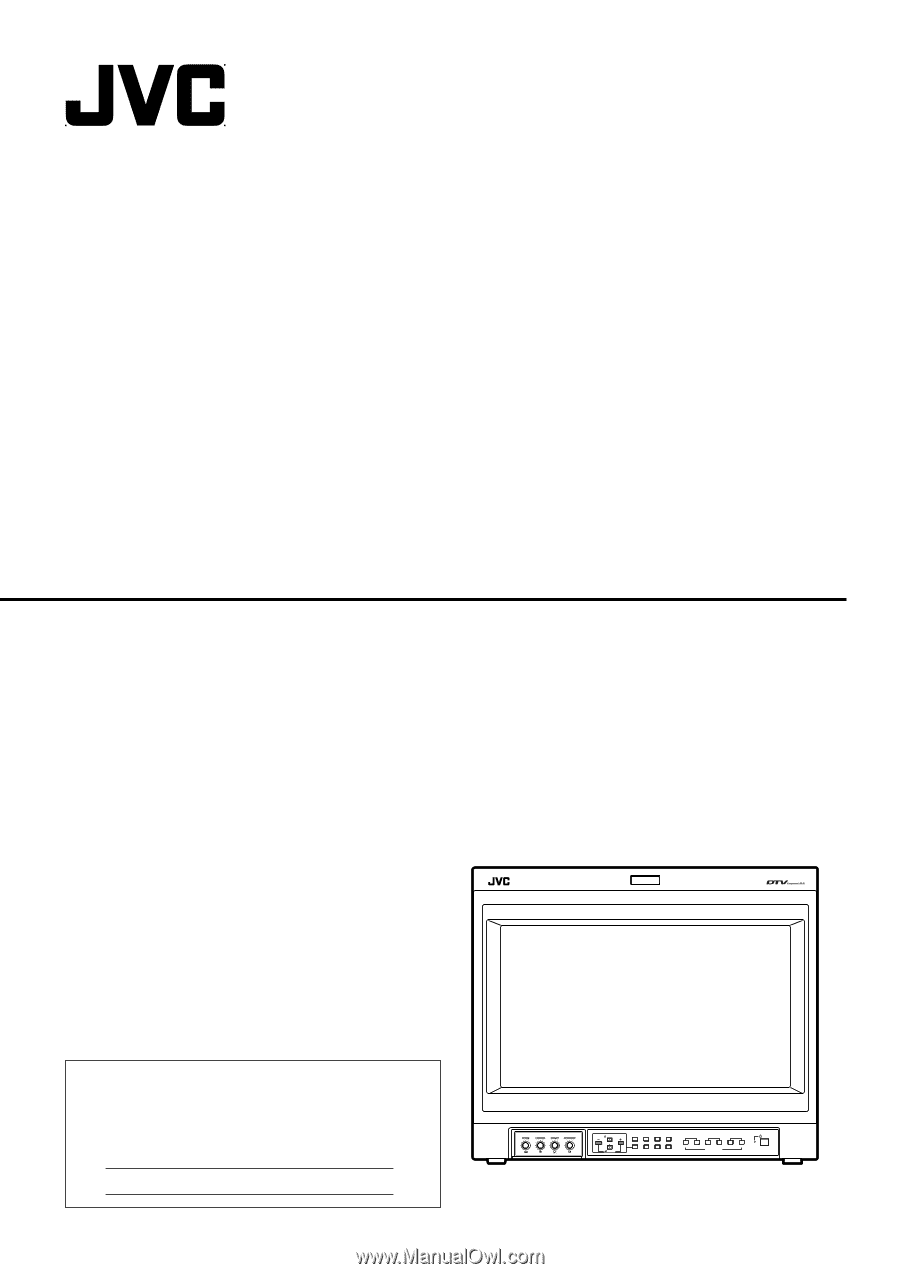
MULTI-FORMAT MONITOR DT-V1910CG DT-V1710CG INSTRUCTIONS For Customer Use: Enter below the Serial No. which is located on the rear of the cabinet. Retain this information for future reference. Model No. : DT-V1910CG/DT-V1710CG Serial No. : MUTING VOLUME UNDER DEGAUSS SCAN PULSE CROSS COLOR OFF - JVC DT-V1710CGU | Instruction Manual - Page 2
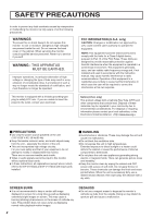
not approved by JVC could void instruction manual serviceable parts inside. ● Video or audio signals cannot be input to this monitor without optional input cards. ● In these instructions, all explanations (except where noted) refer to the DT-V1910CG and DT-V1710CG ray tube. This problem does not occur - JVC DT-V1710CGU | Instruction Manual - Page 3
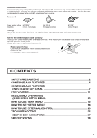
only a correctly rated approved type, re-fit the fuse cover. (Consult your dealer or qualified service personnel.) How to replace the fuse Open the fuse compartment with the blade screw driver, and HOW TO USE EXTERNAL CONTROL 23 TROUBLESHOOTING 25 SELF-CHECK INDICATIONS 27 SPECIFICATIONS 28 3 - JVC DT-V1710CGU | Instruction Manual - Page 4
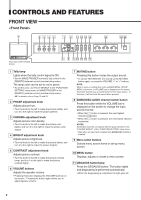
DEGAUSS SCAN PULSE CROSS COLOR OFF MENU SCREENS ASPECT AREA CHECK MARKER SLOT 1 SLOT 2 SLOT 3 A B C D E F INPUT SELECT POWER (Front view of DT-V1910CG shown) MUTING VOLUME UNDER DEGAUSS SCAN PULSE CROSS COLOR OFF MENU SCREENS ASPECT AREA CHECK MARKER SLOT 1 SLOT 2 SLOT - JVC DT-V1710CGU | Instruction Manual - Page 5
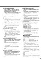
's card slots (SLOT1 - SLOT3). Select SLOT1: press A or B Select SLOT2: press C or D Select SLOT3: press E or F Refer to the input card instructions on pages 7 and 8 for details on the correspondence between the input terminals and the INPUT SELECT buttons. • The INPUT SELECT button corresponding to - JVC DT-V1710CGU | Instruction Manual - Page 6
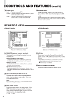
IN OUT SLOT1 SLOT2 REMOTE MAKE/TRIGGER RS-485 IN OUT 21 22 SLOT3 MAIN POWER 23 24 25 (Rear view of DT-V1910CG shown) (Side view of DT-V1910CG shown) 21 REMOTE (external control) terminals Terminals for controlling the monitor from an external unit. MAKE/TRIGGER terminal (Upper): Enables - JVC DT-V1710CGU | Instruction Manual - Page 7
CONTROLS AND FEATURES (INPUT CARD: OPTIONAL) Ⅵ COMPONENT/RGB INPUT CARD (IF-C01COMG) G/Y IN OUT B/PB/B-Y 1 IN OUT R/PR/B-Y IN OUT HD/CS 4 IN OUT VD 2 IN OUT AUDIO 3 IN OUT Ⅵ Compatible signal formats: 480/60i, 576/50i, 576/50p, 480/60p, 720/60p, 1035/60i, 1080/50i, 1080/60i, - JVC DT-V1710CGU | Instruction Manual - Page 8
CONTROLS AND FEATURES (INPUT CARD: OPTIONAL) (cont'd) Ⅵ SDI INPUT CARD (IF-C01SDG) SWITCHED OUT 1 IN SDI 1 2 IN SDI 2 4 AUDIO 1 IN OUT 3 AUDIO 2 Ⅵ Compatible signal formats: 480/60i, 576/50i 1 SWITCHED OUT terminal Output (OUT) terminal for the re-clocked signal. The input signal from - JVC DT-V1710CGU | Instruction Manual - Page 9
Ⅵ SDI INPUT CARD (IF-C21SDG/IF-C51SDG) Compliant with EMBEDDED AUDIO and AUTO INPUT (the SDI input card IF-C51SDG is equipped with an AUDIO LEVEL METER function) SWITCHED OUT 1 IN1 2 E.AUDIO SDI IN2 4 AUDIO MONITOR OUT 3 Ⅵ Compatible signal formats: 480/60i, 576/50i, EMBEDDED AUDIO 1 - JVC DT-V1710CGU | Instruction Manual - Page 10
CONTROLS AND FEATURES (INPUT CARD: OPTIONAL) (cont'd) Ⅵ HD SDI INPUT CARD (IF-C21HSDG/IF-C51HSDG) Compliant with EMBEDDED AUDIO and AUTO INPUT (the HD AD SDI input card IF-C51HSDG is equipped with the AUDIO LEVEL METER function) E.AUDIO HD SDI 1 IN 1 OUT 3 AUDIO MONITOR OUT 2 Ⅵ Compatible - JVC DT-V1710CGU | Instruction Manual - Page 11
side of the DT-V1910CG Multi-Format Monitor 3. Insert the Input Card's board (greencolored) into the slot, fitting the board into the guide rails on the (fix 2 screws each to both right and left side). SLOT1 SLOT2 SLOT3 Guide rails Input card (the illustration Knob shown is of the IF-C01PNG) 4. - JVC DT-V1710CGU | Instruction Manual - Page 12
PREPARATION (cont'd) Ⅵ ATTACHING THE POWER CORD HOLDER • The provided Power Cord Holder prevents accidental disconnection of the AC power cord from the AC inlet. • The Power Cord Holder consists of two parts; a case and cover. 1. Attach the Power Cord Holder case to the AC inlet on the back of the - JVC DT-V1710CGU | Instruction Manual - Page 13
BASIC MENU OPERATIONS (MAIN MENU, SETUP MENU) Ⅵ ABOUT MENU SCREENS This monitor features a MAIN MENU (main menu screen) and a SETUP MENU (setup menu screen). The MAIN MENU contains the functions normally used, and the SETUP MENU contains the settings required for initial setup. "MAIN MENU" Items - JVC DT-V1710CGU | Instruction Manual - Page 14
BASIC MENU OPERATIONS (MAIN MENU, SETUP MENU) (cont'd) Ⅵ DISPLAYING THE MENU SCREENS ⅷ To display MAIN MENU Press the MENU button on the front panel. ⅷ To display SETUP MENU Press the button while pressing the button on the front panel. NOTES: • To exit the MENU, press the MENU button several times - JVC DT-V1710CGU | Instruction Manual - Page 15
HOW TO USE "MAIN MENU" Ⅵ "MAIN MENU" SCREENS MAIN MENU APERTURE CONTROL SLOT CONDITION sub menu POSITION :LOWER AREA MARKER. COLOR MATRIX EXIT:MENU ENTER:+ SELECT: Some items are not displayed depending on the picture input signal. (੬ See page 13.) Press . ੬ See page 16. Setting Items - JVC DT-V1710CGU | Instruction Manual - Page 16
HOW TO USE "MAIN MENU" (cont'd) Ⅵ ITEM CONTENTS AND ADJUSTMENT RANGE/SETTINGS APERTURE CONTROL AREA MARKER: Compensates the frequency characteristics of the input video signal. Press the button to display the setting menu illustrated on the right. LEVEL CONTROL FREQ. sub - JVC DT-V1710CGU | Instruction Manual - Page 17
the standard of the color demodulation (color rendering). Press the button to display the setting menu illustrated on the right. SELECT :MANUAL R-Y PHASE : 90 R/B GAIN :0.86 G-Y PHASE : 244 G/B GAIN :0.36 sub menu reset EXIT: MENU ADJUST:- + SELECT: The menu screen when - JVC DT-V1710CGU | Instruction Manual - Page 18
HOW TO USE "SETUP MENU" Ⅵ "SETUP MENU" SCREENS SETUP MENU Setting Items FUNCTION SETTING PICTURE SUB ADJ. COLOR TEMP./BAL. SIZE/POSI.ADJ. DISTORTION ADJ. STATUS DISPLAY CONTROL LOCK all reset :ON EXIT:MENU ENTER:+ SELECT: Press . COLOR SYSTEM AUTO INPUT SYNC - JVC DT-V1710CGU | Instruction Manual - Page 19
Ⅵ ITEM CONTENTS AND ADJUSTMENT RANGE/SETTINGS FUNCTION SETTING Selects the control systems for the COLOR SYSTEM, synchronized signal, RUSH DELAY TIME, tally lamp colors, and MAKE/TRIGGER terminal. • Checks the amount of time that the monitor has been used. • Sets the AUTO INPUT function ON/OFF. ( - JVC DT-V1710CGU | Instruction Manual - Page 20
HOW TO USE "SETUP MENU" (cont'd) PICTURE SUB ADJ. Controls the approximate adjustment of the video control level when the video adjustment knob is adjusted to the center. • Can also be used to switch the NTSC set-up level, and change the component signal's input level settings. Press the button - JVC DT-V1710CGU | Instruction Manual - Page 21
SIZE/POSI. ADJ. Adjusts the size or position of the picture. Press the button to display the setting menu illustrated on the right. H.SIZE H.POSITION V.SIZE V.POSITION ZOOM H.SIZE ZOOM V.SIZE sub menu reset : 00 : 00 : 00 : 00 : 00 : 00 EXIT: MENU ADJUST:- + SELECT: - JVC DT-V1710CGU | Instruction Manual - Page 22
HOW TO USE "SETUP MENU" (cont'd) STATUS DISPLAY Sets the status display ON/OFF. * Switches the display on and off. Also selects the type of display. (When an input card compliant with AUDIO LEVEL METER is installed.) * Switches the AUDIO PLL setting. (When SDI input card compliant with EMBEDDED - JVC DT-V1710CGU | Instruction Manual - Page 23
HOW TO USE EXTERNAL CONTROL Ⅵ ABOUT EXTERNAL CONTROL The Multi-Format Monitor has two external control terminals. One is the MAKE/TRIGGER terminal, which allows the monitor to be controlled by the MAKE(make contact) or TRG. (trigger contact) method selected in the function setting. MAKE (make - JVC DT-V1710CGU | Instruction Manual - Page 24
) or your PC via the RS-485 terminal. For details on operating the monitor from the PC, consult the service center. 1. Cable Prepare a straight cable with a D-sub connector (9-pin, male) and a D-sub connector (9-pin, male) 5 9 4 8 7 3 2 6 1 2. Communications Specifications Baud Rate - JVC DT-V1710CGU | Instruction Manual - Page 25
TROUBLESHOOTING Solutions to common problems related to your monitor are described here. If none of the solutions presented here solve the problem, unplug the monitor and consult a JVC-authorized dealer or service center for assistance. Problems No power supply No picture with the power on No - JVC DT-V1710CGU | Instruction Manual - Page 26
TROUBLESHOOTING (cont'd) Problems Irregular color Wrong picture position, wrong picture size Front MARKER SLOT 1 SLOT 2 SLOT 3 A B C D E F INPUT SELECT POWER (Front view of DT-V1910CG shown) ● About CRT tube reflection (when Zoom mode is used.) The screen might appear as brownish - JVC DT-V1710CGU | Instruction Manual - Page 27
it to detect malfunctions and alert you. This makes trouble-shooting easier. Whenever a problem occurs, a combination of "self-check indicators" ( 2 SLOT 3 A B C D E F INPUT SELECT POWER (Front view of DT-V1910CG shown) 1. Check which indicators are blinking. 2. Turn off the main power - JVC DT-V1710CGU | Instruction Manual - Page 28
input card is inserted) Dimensions Weight Accessory DT-V1910CG DT-V1710CG Multi-Format Monitor Multi-Format Monitor 19" 1 Screws x 4 (Wide Mask) * Illustrations and pictures used in this manual have been exaggerated, abbreviated or compounded for explanatory purposes only. The appearance of - JVC DT-V1710CGU | Instruction Manual - Page 29
CROSS COLOR OFF MENU SCREENS ASPECT AREA CHECK MARKER SLOT 1 SLOT 2 SLOT 3 A B C D E F INPUT SELECT 380.4 (15") POWER [DT-V1710CG] 5 (1/4") 95.7 (3-7/8") 336 (13-1/4") 5 (1/4") Asterisks(*) are used to indicate front panel dimensions - JVC DT-V1710CGU | Instruction Manual - Page 30
SPECIFICATIONS (cont'd) Ⅵ Compliant Signal Formats of Each Input Card Input Signals NTSC (3.58 MHz) PAL (4.43 MHz) Black-and-White (50 Hz/60 Hz) 480/60i (525i) 480/60p (525p) 576/50i 576/50p 720/50p (720p) 720/60p (720p) 1080/50i 1080/60i (1125i) 1035/60i (1125i) (*1) 1080/24psF EMBEDDED AUDIO IF - JVC DT-V1710CGU | Instruction Manual - Page 31
and dip switch array S102 on the lower part. The surface of these switches is pre-coated with a film on shipment from the factory. When problems arise, such as not being able to set functions properly with the dip switches, be sure to check the following: S101 Dip switch array S101 - JVC DT-V1710CGU | Instruction Manual - Page 32
JVC PROFESSIONAL PRODUCTS COMPANY DIVISION OF US JVC CORP. 1700 Valley Road Wayne, N.J. 07470 JVC CANADA INC. 21 Finchdene Square, Scarborough Ontario M1X 1A7 © 2003 VICTOR COMPANY OF JAPAN, LIMITED Printed in Japan 0403-MA-CR-VP DT-V1910CG/DT-V1710CG MULTI-FORMAT MONITOR
-
 1
1 -
 2
2 -
 3
3 -
 4
4 -
 5
5 -
 6
6 -
 7
7 -
8
-
9
-
10
-
11
-
12
-
13
-
14
-
15
-
16
-
17
-
18
-
19
-
20
-
21
-
22
-
23
-
24
-
25
-
26
-
27
-
28
-
29
-
30
-
31
-
32
 |
 |
INSTRUCTIONS
DT-V1910CG
DT-V1710CG
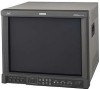
MULTI-FORMAT MONITOR
VOLUME
SLOT 1
A
B
DEGAUSS
MENU
MUTING
SCREENS
CHECK
ASPECT
AREA
MARKER
UNDER
SCAN
PULSE
CROSS
COLOR
OFF
SLOT 2
C
D
SLOT 3
POWER
E
F
INPUT SELECT
For Customer Use:
Enter below the Serial No. which is located on the rear of
the cabinet. Retain this information for future reference.
Model No.
:
DT-V1910CG/DT-V1710CG
Serial No.
:
The illustration shows the DT-V1910CG with provided wide mask attached.
LCT1424-001A