JVC DT-V1710CGU Instruction Manual - Page 22
cont'd
 |
UPC - 046838208102
View all JVC DT-V1710CGU manuals
Add to My Manuals
Save this manual to your list of manuals |
Page 22 highlights
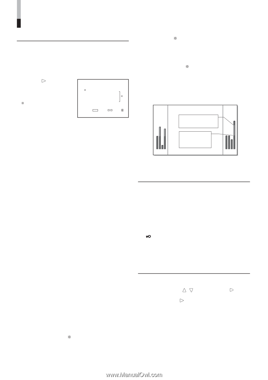
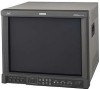
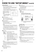
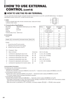
HOW TO USE "SETUP MENU" (cont'd) STATUS DISPLAY Sets the status display ON/OFF. * Switches the display on and off. Also selects the type of display. (When an input card compliant with AUDIO LEVEL METER is installed.) * Switches the AUDIO PLL setting. (When SDI input card compliant with EMBEDDED AUDIO is installed.) Press the button to display the setting menu illustrated on the right. NOTE: Function setting is displayed when input card compliant with AUDIO LEVEL METER is installed. STATUS DISPLAY LEVEL METER ch BAR TYPE REFERENCE LEVEL OVER LEVEL BAR BRIGHTNESS : ON :31•24 :3COLORS : -20dB : -4dB : HIGH EXIT: MENU ADJUST:- + SELECT: Ⅵ STATUS DISPLAY Sets the status display ON or OFF. ON : The information is displayed. OFF : The information is not displayed. Ⅵ LEVEL METER ch Selects the audio channels used in the AUDIO LEVEL METER display. • OFF/1:2/12:34/31:24/123:456/1-8 NOTES: • Numbers indicate the audio channel. The channel input level indicated on the left side of ":" is displayed on the left side of the screen, and the channel input level indicated on the right side of ":" is displayed on the right side of the screen. • AUDIO LEVEL METER is not displayed when this is set to OFF. • When "1-8" is selected, the channel input level for 1, 2, 3 and 4 is displayed on the left side of the screen, and the channel input level for 5, 6, 7 and 8 is displayed on the right side of the screen. Ⅵ BAR TYPE Selects the color of the audio level meter. WHITE-1 : White color display WHITE-2 : White (half transparent) display 3 COLORS : The audio level meter uses three different colors (red, yellow and green) to indicate variations in input levels. Red Yellow : displayed when the audio input exceeds the level set in "OVER LEVEL". : displayed when the audio input exceeds the level set in "REFERENCE LEVEL". Green : displayed when the audio input does not exceed the level set in "REFERENCE LEVEL". NOTES: • For WHITE-1 and WHITE-2, the line indication for the standard input level set in the "REFERENCE LEVEL" is displayed. Input level set in the "OVER LEVEL" is not displayed. • As for the audio channel bar display with no signal input, white is displayed for the 3COLORS setting, and gray is displayed for other settings. Ⅵ REFERENCE LEVEL ( ) Sets the standard input level. • -20dB/-18dB Ⅵ OVER LEVEL ( ) Sets the input level's lower limit indicated in red for the "3COLORS" display. • -8dB/-6dB/-4dB/-2dB Ⅵ BAR BRIGHTNESS ( ) Selects the brightness of the AUDIO LEVEL METER display. HIGH : Brighter LOW : Darker AUDIO LEVEL METER display example LEVEL METER ch: 1-8, BAR TYPE: 3COLORS OVER LEVEL [-8dB/-6dB/-4dB/-2dB] REFERENCE LEVEL [-20dB/ -18dB] 1 2 3 4 Audio channels and OVER/REFERENCE 5 6 7 8 level indication CONTROL LOCK Ⅵ CONTROL LOCK Invalidates most of operations on the front panel (including menu screen operations). OFF : Enables normal operations. ON : Invalidates all operations except the power switch and CONTROL LOCK. NOTES: • While CONTROL LOCK is set to ON, attempting to perform any operation except power switch and CONTROL LOCK causes the " Control lock on!" warning to appear on the screen for approx. 3 seconds. (It is possible to operate the power switch and display SETUP MENU.) • When SETUP MENU is displayed while CONTROL LOCK is set to ON, the cursor (4) is located next to CONTROL LOCK and cannot be moved. all reset Resets all SETUP MENU items to factory-preset values. 1. Select "all reset" by / buttons, then press button. Confirmation message is displayed. 2. To initialize, press button. To cancel the initialization, press the MENU button. 22
-
 1
1 -
2
-
3
-
4
-
5
-
6
-
7
-
8
-
9
-
10
-
11
-
12
-
13
-
14
-
15
-
16
-
 17
17 -
 18
18 -
 19
19 -
 20
20 -
 21
21 -
 22
22 -
 23
23 -
 24
24 -
 25
25 -
 26
26 -
 27
27 -
28
-
29
-
30
-
31
-
32
 |
 |