JVC DT-V1710CGU Instruction Manual - Page 11
Preparation
 |
UPC - 046838208102
View all JVC DT-V1710CGU manuals
Add to My Manuals
Save this manual to your list of manuals |
Page 11 highlights
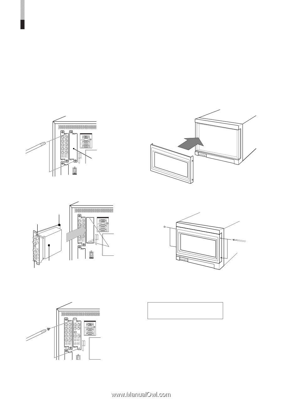
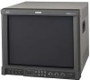
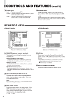
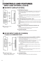
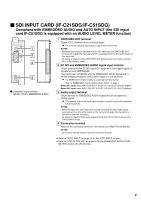
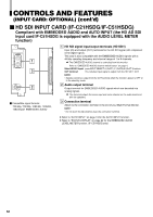
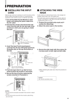
PREPARATION Ⅵ INSTALLING THE INPUT CARD Optional input cards are necessary to use the functions of this monitor. Before mounting the monitor or connecting other equipment to the monitor, be sure to install the input cards. 1. Turn off the Multi-Format Monitor's main power and unplug the power cable from the AC outlet. 2. Unscrew the screws and remove the slot cover from the slot (on the rear side of the monitor) in which you are going to install the card. Ⅵ ATTACHING THE WIDE MASK A wide mask is provided with the monitor. This changes the viewable screen area to the 16:9 aspect ratio. • The wide mask cannot be attached to the monitor after the monitor is mounted in a rack. Mount the wide mask before installing the monitor in a rack. 1. Prepare the provided wide mask and 4 screws (for attaching). 2. Attach the wide mask to the monitor. REMOTE MAKE/TRIGGER RS-485 IN OUT SLOT1 SLOT2 SLOT3 Slot cover Rear side of the DT-V1910CG Multi-Format Monitor 3. Insert the Input Card's board (greencolored) into the slot, fitting the board into the guide rails on the top and bottom of the slot. Fit the board to the guide rails. Knob REMOTE MAKE/TRIGGER RS-485 IN OUT 3. Secure the wide mask with the screws (fix 2 screws each to both right and left side). SLOT1 SLOT2 SLOT3 Guide rails Input card (the illustration Knob shown is of the IF-C01PNG) 4. Push the Input Card in so that its front panel touches the monitor's rear panel. 5. Secure the Input Card by replacing the screws removed in Procedure 2. REMOTE MAKE/TRIGGER RS-485 IN OUT ● When detaching the wide mask, follow this procedure in reverse. Caution: Use only the provided screws. SLOT1 SLOT2 SLOT3 NOTES: • Do not touch the terminal connected to the monitor or board pattern. • Do not remove slot covers from the monitor's slots if they are not in use. 11
-
 1
1 -
2
-
3
-
4
-
5
-
 6
6 -
 7
7 -
 8
8 -
 9
9 -
 10
10 -
 11
11 -
 12
12 -
 13
13 -
 14
14 -
 15
15 -
 16
16 -
17
-
18
-
19
-
20
-
21
-
22
-
23
-
24
-
25
-
26
-
27
-
28
-
29
-
30
-
31
-
32
 |
 |