Kyocera TASKalfa 181 Fax System (R) Installation Instructions - Page 9
Collegamento della linea del telefono al terminale della linea.
 |
View all Kyocera TASKalfa 181 manuals
Add to My Manuals
Save this manual to your list of manuals |
Page 9 highlights
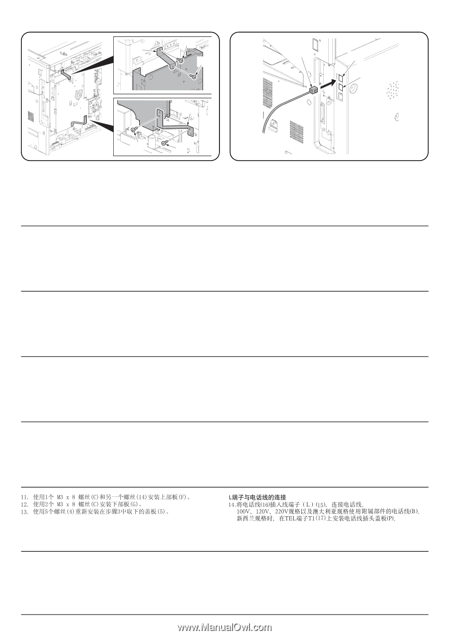
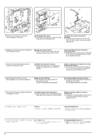
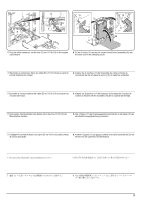
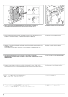
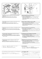
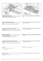
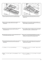
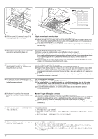
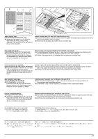
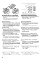
14 F C 16 15 17 G C C 11. Attach the upper plate (F) using an M3 x 8 screw (C) and another screw (14). 12. Attach the lower plate (G) using two M3 x 8 screws (C). 13. Refit the cover (5) removed in step 3 using 5 screws (4). Connect the telephone line to the line terminal. 14.Insert the modular connector cable (16) to the line terminal (15) to connect it to the telephone line. For 100 V, 120 V or 220 V specification or for Australia, use the supplied modular cord (B). In New Zealand, attach the modular connector cover (P) to the TEL terminal T1 (17). 11. Fixez le plateau supérieur (F) à l'aide d'une vis M3 x 8 (C) et d'une autre vis (14). 12. Fixez le plateau inférieur à l'aide de deux vis M3 x 8 (C). 13. Réinstallez le capot (5) déposé à l'étape 3 à l'aide de 5 vis (4). Connecter la ligne de téléphone à la borne de ligne. 14.Insérer le câble du connecteur modulaire (16) dans la borne de la ligne (15) pour le connecter à la ligne de téléphone. Pour les spécifications 100 V, 120 V ou 220 V ou pour l'Australie, utiliser le cordon modulaire fourni (B). En Nouvelle-Zélande, fixer le couvercle du connecteur modulaire (P) à la borne TEL T1 (17). 11. Instalar la placa superior (F) por medio de un tornillo M3 x 8 (C) y otro tornillo (14). 12. Instalar la placa inferior (G) por medio de dos tornillos M3 x 8 (C). 13. Volver a colocar, con los 5 tornillos (4), la cubierta (5) desmontada en el paso 3. Conecte la línea telefónica en el terminal de línea. 14.Inserte el cable de conector modular (16) en el terminal de línea (15) para conectarlo a la línea telefónica. Para especificaciones de 100 V, 120 V o 220 V o para Australia, utilice el cable modular (B). Para Nueva Zelandia, instale la cubierta del conector modular (P) en el terminal TEL T1 (17). 11. Die obere Platte (F) mittels einer M3 x 8 Schraube (C) und einer weiteren Schraube (14) befestigen. 12. Die untere Platte (G) mittels zwei M3 x 8 Schrauben (C) befestigen. 13. Die in Schritt 3 entfernte Abdeckung (5) mittels der 5 Schrauben (4) wieder anbringen. Die Telefonleitung an die Leitungsbuchse anschließen. 14.Das Modularsteckerkabel (16) in die Leitungsbuchse (15) stecken, um sie mit der Telefonleitung zu verbinden. Für die 100-, 120- oder 220-V-Spezifikationen oder für Australien ist das mitgelieferte Modulkabel (B) zu verwenden. Für Neuseeland: Die Modulsteckerabdeckung (P) an der TEL-Klemme T1 (17) anbringen. 11. Fissare la piastra superiore (F) utilizzando una vite M3 x 8 (C) e un'altra vite (14). 12. Fissare la piastra inferiore (G) utilizzando due viti M3 x 8 (C). 13. Ricollocare il coperchio (5) rimosso al passo 3 utilizzando le 5 viti (4). Collegamento della linea del telefono al terminale della linea. 14.Inserite il cavo modulare del connettore (16) al terminale della linea (15) per collegarlo alla linea del telefono. Per i modelli con specifica 100 V, 120 V o 220 V o per l'Australia, utilizzare il cavo modulare (B) fornito in dotazione. In Nuova Zelanda, fissare il coperchio del connettore modulare (P) al terminale TEL T1 (17). 11.ビス (14)1 M3 × 8(C)1 F 12.ビス M3 × 8(C)2 G 13.手順 3 5 4)5 L 14 L(15 16 100V,120V,220V B TEL 端子 T1(17 P 7
-
 1
1 -
2
-
3
-
 4
4 -
 5
5 -
 6
6 -
 7
7 -
 8
8 -
 9
9 -
 10
10 -
 11
11 -
 12
12 -
 13
13 -
 14
14 -
15
-
16
-
17
-
18
-
19
-
20
 |
 |