LG LSC121PMA Service Manual
LG LSC121PMA Manual
 |
View all LG LSC121PMA manuals
Add to My Manuals
Save this manual to your list of manuals |
LG LSC121PMA manual content summary:
- LG LSC121PMA | Service Manual - Page 1
Room Air Conditioner SERVICE MANUAL MODEL : LSC091PMA LSC121PMA - LG LSC121PMA | Service Manual - Page 2
...6 Dimensions ...7 Refrigeration Cycle Diagram 9 Wiring Diagram...10 Operation Details ...11 Display Function ...17 Self-diagnosis Function...17 Installation ...18 Operation ...33 Disassembly of the parts (Indoor Unit 33 2-way, 3-way Valve...35 Cycle Troubleshooting Guide 42 Electronic Control - LG LSC121PMA | Service Manual - Page 3
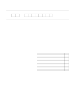
Details of 2003 LG Model Name 12 - 3 4 5 6 7 8 9 10 Code 1 2 3 4,5 6 7 8 9 Type Code of Model Meaning Producing Center/ A~Z Refrigerant L: ChangWon R22, A: ChangWon R410A, C: ChangWon R407C Type of Air conditioner A~Z S: Split Type Air conditioner Cooling/Heating A~Z C: C/O, H: H/P, - LG LSC121PMA | Service Manual - Page 4
Operation indication Lamps (LED) Signal Receptor Receives the signals from the remote control.(Signal receiving sound: two short beeps or one long beep.) Operation Indication Lamps On/Off : Lights up during the system operation. Sleep Mode : Lights up during Sleep Mode Auto operation. - LG LSC121PMA | Service Manual - Page 5
Remote Control Operation ON/OFF Operation Mode Selection (Cooling (Heating model only) model only) Cooling Operation Mode.( ) Healthy Dehumidification Operation Mode.( Fan Speed Selection Auto Operation - LG LSC121PMA | Service Manual - Page 6
Operation Healthy Dehumidification Mode Restart Delay minutes Refrigerant(R-22) Charge g(oz) Power cord AWG 540*245 30.3*21.3*9.6 7(15.4) 33(72.8) LSC121PMA 1, 115, 60 12,000 1,290 11.7 58 9.3 8.8(330) 1.4(3) 43 37 34 46 Thermistor 4-way 3/4 Auto Manual Wireless LCD 64~86°F 2°F Yes Yes 24hr, - LG LSC121PMA | Service Manual - Page 7
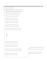
Dimensions (1) Indoor Unit (9K, 12K) W D H Hanger Hole Pipe Hole Fix Hole MODEL DIM Unit W mm(inch) H mm(inch) D mm(inch) INDOOR UNIT 570(22.4) 568(22.3) 137(5.4) -7- - LG LSC121PMA | Service Manual - Page 8
(2) Outdoor Unit (9K, 12K) W L2 D L1 L3 H L4 MODEL DIM unit W mm(inch) H mm(inch) D mm(inch) L1 mm(inch) L2 mm(inch) L3 mm(inch) L4 mm(inch) L5 mm(inch) L5 Gas side (3-way valve) Liquid side (2-way valve) All Models 770(30.3) 540(21.3) 245(9.6) 287(11.3) 64(2.5) 518(20.4) - LG LSC121PMA | Service Manual - Page 9
1/4" Piping length Rated Max 7.62m(25ft) 15m(50ft) Elevation Rated Max 5m(16ft) 7m(23ft) For installation over rated, *a proper quantity of refrigerant should be added for each meter. a proper quantity of refrigerant 9K, 12K 20g Ex) 9K: When installed at a distance of 15m, 148g of - LG LSC121PMA | Service Manual - Page 10
Wiring Diagram (1) Indoor Unit 9K, 12K (Cooling Only Models, Cooling & Heating Models) CAPACITOR C F CN-TRANS TRANSFORMER (2) Outdoor Unit (9K, 12K) BL MAIN P.C.B RD YL T/B 1 BL BL BR ZNR BK MOTOR RD FUSE 3.15A BK RY-COMP 3 4 CN-POWER CN-DC/DC BR BL RD BR BK BL FUSE 2.5A H BR - LG LSC121PMA | Service Manual - Page 11
Indicator • ON while in sleep timer mode, OFF when sleep timer cancel or appliance operation pause. Timer Indicator • ON while in timer mode (on/off), OFF Dehumidification Mode • When the dehumidification operation input by the remote control is received, the intake air temperature is detected - LG LSC121PMA | Service Manual - Page 12
• While in compressor off, the indoor fan repeats low airflow speed and pause. • While the intake air temp is between compressor on temp. and compressor off temp., 10-min dehumidifica- tion operation and 4-min compressor off repeat. Compressor ON Temp. ➲ Setting Temp+0.5°C Compressor OFF Temp. ➲ - LG LSC121PMA | Service Manual - Page 13
s Fuzzy Operation (C/O Model) • According to the temperature set by Fuzzy rule, when the intake air temp is 0.5°C or more below the setting temp, the compressor is turned off. When 0.5°C or more above the setting temp, the compressor is turned on. Compressor ON Temp ➲ Setting Temp + 0.5°C - LG LSC121PMA | Service Manual - Page 14
, low, or chaos (auto) by the input of the airflow speed selection key on the remote control. s On-Timer Operation • When the set time is reached after the time is input by the remote control, the appliance starts to operate. • The timer LED is on when the on-timer is input. It is - LG LSC121PMA | Service Manual - Page 15
Sleep Timer Operation • When the sleep time is reached after is input by the remote control while in appliance operation, the operation of the appliance stops. • While the appliance is on pause, the sleep timer mode cannot be input. • While in cooling mode operation, 30 - LG LSC121PMA | Service Manual - Page 16
on according to the condition of the room temperature. s Buzzer Sounding Operation • When the appliance-operation key is input by the remote control, the short "beep-beep-" sounds. • When the appliance-pause key is input by the remote control, the long "beep-" sounds. • When a key is input by the - LG LSC121PMA | Service Manual - Page 17
Display Function 1. Heating Model Operation Indicator • Cooling, Soft Dry, Fan, Heating Sleep Timer Indicator • Sleep Mode Timer Indicator • Timer Mode Defrost Indicator • Hot-start, Defrost 2. Cooling Model Operation Indicator • Cooling, Soft Dry, Fan Sleep Timer Indicator • Sleep Mode Timer - LG LSC121PMA | Service Manual - Page 18
Capacity Pipe Size (Btu/h) GAS LIQUID 9K 1/2" 1/4" 12K 1/2" 1/4" Standard Length (m) 7.5 (24.6ft) 7.5 (24.6ft) Max. Max. Additional Elevation length Refrigerant B (m) A (m) (g/m) 7 15 (23ft) (50ft) 20 7 15 (23ft) (50ft) 20 More than 2m(6.6ft) More than 50cm(19.7") Outdoor unit Indoor - LG LSC121PMA | Service Manual - Page 19
3) Preparing work for Installation 1. Open panel front s First,Pull the grille bottom, then remove screws(2 pieces), and close grille bottom again. s The moment of lifting the both lower parts of panel front, you can hear sound this panel came out, In this time panel front is separated s After pull - LG LSC121PMA | Service Manual - Page 20
hole of product at the upper screws. (In this time, Remove the map) (Falling attention) INSTALLATION GUIDE MAP In case of nothing wrong in the matter, connect the pipe and the wire. (Installation manual reference) Hanger hole (Rear side of product) 5. Check the fixed product with light power - LG LSC121PMA | Service Manual - Page 21
2. Flaring Work and Connection of Piping 1) Flaring work Main cause for gas leakage is due to defect in flaring work. Carry out correct flaring work in the following procedure. 1. Cut the pipes and the cable. s Use the piping kit accessory or the pipes purchased locally. s Measure the distance - LG LSC121PMA | Service Manual - Page 22
2. Tape the tubing, drain hose and the connecting cable. Be sure that the drain hose is located at the lowest side of the bundle. Locating at the upper side can cause drain pan to overflow inside the unit. s When extending the drain hose at the indoor unit, install the drain pipe. Drain pipe - LG LSC121PMA | Service Manual - Page 23
Information (For right piping) • Good case For right piping, follow the instruction below. s Press on the upper side of clamp and unfold the tubing to Following bending type from right to left could cause problem of pipe damage. OOuuttddoooorr uunniitt Outdoor unit GLiaqsuisdidseidpeippinipging - LG LSC121PMA | Service Manual - Page 24
1/2". Refer to "How to connect wiring to the terminals" for instructions on connecting depending on the wire type you are using. WARNING • wire must be connected firmly. • No wire should be allowed to touch refrigerant tubing, the compressor or any moving parts. Power Supply Model Power source - LG LSC121PMA | Service Manual - Page 25
A fire hazard may also exist. Therefore, be sure all wiring is tightly connected. When connecting each power wire to the corresponding terminal, follow instructions "How to connect wiring to the terminals" and fasten the wire tightly with the fixing screw of the terminal plate. How to connect wiring - LG LSC121PMA | Service Manual - Page 26
4. checking the Drainage and forming the pipings 1) Checking the drainage 1. To check the drainage. s Pour a glass of water on the evaporator. s Ensure the water flows through the drain hose of the indoor unit without any leakage and goes out the drain exit. 2) Form the piping 1. Form the piping - LG LSC121PMA | Service Manual - Page 27
the correct field wiring. Wrong wiring can cause the unit to misoperate to result in a fire hazard. • Check local electrical codes and any specified wiring instructions or limitations. Connecting cable -27- - LG LSC121PMA | Service Manual - Page 28
Connect the manifold valve(with pressure gauges) and dry nitrogen gas cylinder to this service port with charge hoses. CAUTION Be sure to use a manifold valve for air purging soap. CAUTION To avoid nitrogen entering the refrigerant system in a liquid state, the top of the cylinder must be higher - LG LSC121PMA | Service Manual - Page 29
fasten the flare nut securely with an adjustable wrench. This process is very important to prevent leakage from the system. • Replace the valve caps at both gas and liquid side service valves and fasten them tight. This completes air purging with a vacuum pump. The air conditioner is now ready to - LG LSC121PMA | Service Manual - Page 30
6. Panel Front Assembly 1. First, Check the side cover assembly exactly, Fix power cord in the bottom groove of cover side left. 2. Assemble connecting lead wire with controller and first fix the upper part of panel front, then match the lower part of panel front Panel Front Connector 3. Drive - LG LSC121PMA | Service Manual - Page 31
. Do not use recharge- able batteries. • Remove the batteries from the remote control if the system is not going to be used for a long time. 2. Settlement of 20 minutes, then check the system refrigerant charge: 1. Measure the pressure of the gas side service valve. 2. Measure the temperature - LG LSC121PMA | Service Manual - Page 32
Operation Name and Function-Remote Control The remote control transmits the signals to the system. Signal transmitter 5 1 6 3 4 2 10 CANCEL 7 9 ON OFF SET 11 AUTO CLEAN 8 12 13 14 Flip-up door (opened) Operation Mode Cooling Operation Auto Operation Healthy Dehumidification - LG LSC121PMA | Service Manual - Page 33
Disassembly of the parts (Indoor unit) Warning : Disconnect the unit from power supply before making any checks. Be sure the power switch is set to "OFF". 1. To remove the Grille from the Chassis. - Pull the grille bottom, the remove 2 securing screws. - Lift the both lower parts of panel front. - - LG LSC121PMA | Service Manual - Page 34
carefully. 4. Before removing the Turbo Fan. - Remove the securing screws from the chassis. - Pull the pipe cover, top cover and the air guide. Top Cover Air Guide 5. To remove the Motor. - Remove the securing bolt from the motor shaft. - Pull the fan out from the motor shaft. - Remove 4 screws - LG LSC121PMA | Service Manual - Page 35
) Shaft position Closed (with valve cap) Open (counter-clockwise) Open (with valve cap) Closed (clockwise) Open Open Open Open -35- Shaft position Service port Closed (with valve cap) Closed (with cap) Closed (clockwise) Open (push-pin or with vacumm pump) Open (with valve cap) Closed - LG LSC121PMA | Service Manual - Page 36
Service port nut: Be sure, using a torque wrench to tighten the service port nut (after using the service port), so that it prevents the gas leakage from the refrigeration air from the system. - Set the 2-way valve to the open position and remove the cap from the 3-way valve's service port. - Using - LG LSC121PMA | Service Manual - Page 37
for 10 to 15 minutes. (3) Stop operation and wait for 3 minutes, then connect the charge set to the service port of the 3-way valve. - Connect the charge hose with the push pin to the service port. (4) Air purging of the charge hose. - Open the low-pressure valve on the charge set slightly - LG LSC121PMA | Service Manual - Page 38
and discharge the refrigerant until the gauge indicates 3 to 5 kg/cm2g. (6) Disconnect the charge set and the gas cylinder, and set the 2-way and 3-way valves to the open position. - Be sure to use a hexagonal wrench to operate the valve stems. (7) Mount the valve stem nuts and the service port nut - LG LSC121PMA | Service Manual - Page 39
closed. - Connect the charge hose with the push pin to the service port. (3) Open the valve (Lo side) on the charge set and discharge the refrigerant until the gauge indicates 0 kg/cm2G. - If there is no air in the refrigerant cycle (the pressure when the air conditioner is not running is higher - LG LSC121PMA | Service Manual - Page 40
3. Evacuation (All amount of refrigerant leaked) Indoor unit Liquid side 2-Way valve Open Outdoor unit Gas side 3-Way valve Open Vacuum pump OPEN Lo CLOSE • Procedure (1) Connect the vacuum pump - LG LSC121PMA | Service Manual - Page 41
the air conditioner. (4) Immediately disconnect the charge hose from the 3-way valve's service port. - Stopping partway will allow the gas to be discharged. - If the system has been charged with liquid refrigerant while operating the air conditioner turn off the air conditioner before disconnecting - LG LSC121PMA | Service Manual - Page 42
Troubleshooting Guide 1. Trouble analysis 1. Check temperature difference between intake and discharge air and operating current. Temp. Difference Operating Current Temp. difference :approx. 0°F Current :less than 80% of rated current All amount of refrigerant leaked out. Check refrigeration - LG LSC121PMA | Service Manual - Page 43
2. Product does not operate at all. (* Refer to Electronic Control Device drawing and Schematic diagram.) Turn off Main Power (After 10 seconds) Turn on Main Power Does "beeping" sound is made from the Indoor Unit? NO YES Check the voltage of power(About AC 208V/AC230V, 60Hz) • Main power's - LG LSC121PMA | Service Manual - Page 44
mark( ) is displayed in LCD screen, replace battery. Check the contact of CN-DISP connector. When the detect switch(double key) inside the remote controller door is fault, it is impossible to operate temperature regulating( / ) and wind speed selecting. Check DISP PWB Ass'y - Voltage between CN - LG LSC121PMA | Service Manual - Page 45
Power Operate "Cooling Mode( )" by setting the desired temperature of the remote controller is less than one of the indoor temperature by 2°F at least When the power(About AC200V) is applied to the connecting wire terminal support transferred to compressor, PWB Ass'y is normal. • Check the circuit - LG LSC121PMA | Service Manual - Page 46
5. When Indoor Fan does not operate. Does the voltage of each terminals of CN-MOTOR CONNECTOR in Indoor unit corresponds to values in the Table of page 51? Does the voltage of terminal of CN-DC/DC CONNECTOR in Check connecting condition of the CN-MOTOR Indoor unit corresponds to the values in the - LG LSC121PMA | Service Manual - Page 47
- Between 57 , 56 , 55 and 54 of MICOM - Between 51 , 50 , 49 and 48 of MICOM - Between 1 , 2 , 3 , 4 and 5 of CN-U/D, CN-L/R If there are no problems after above checks • Confirm the assembly conditions that are catching and interfering parts in the rotation radial of the Vertical Louver - 47 - - LG LSC121PMA | Service Manual - Page 48
by the power of Outdoor unit is off. Check for the communication error and the operating condition of product after also operating with the remote controller, then taking above 2 minutes. Check the PWB assembly of Indoor and Outdoor unit. Caution: If the connecting wires of Indoor and Outdoor unit - LG LSC121PMA | Service Manual - Page 49
Indoor unit blinks 8 times. • The up/down vane does not operate. • The up/down vane does not smoothly operate. • It does not operate with a remote controller. • The operation indicator blinks once. On for 0.5 second Off for 3 seconds • The compressor and the outdoor fan stop. • The indoor fan speed - LG LSC121PMA | Service Manual - Page 50
power. • No power for Indoor unit. • The signal input of the remote controller and operation of product is impossible. • The thermal protector of the Trans operates when let it alone for long time. • The signal of the remote controller is inputted. • The fuse and Q61 in the Outdoor unit are damaged - LG LSC121PMA | Service Manual - Page 51
9. Voltage of Connectors according to Indoor Fan Speed - 51 - INDOOR FAN MOTOR INDOOR PWB ASSY 1234 BL BK BR RD Input Power POWER TRANS BK BK BL 12 CN-POWER 123456 CN-TRANS Connecting wires between Indoor and Outdoor Indoor Connecting Terminal Outdoor Connecting Terminal 4 3 RY-COMP CN- - LG LSC121PMA | Service Manual - Page 52
Electronic Control Device (1) MAIN PWB ASSY(Indoor Unit) • TOP VIEW • BOTTOM VIEW • PWB ASSY SVC PART LIST NO MODEL 1 12K Cooling Model 2 9K Cooling Model OJ1H : Short OJ2H, OJ3H, OJ4H : OPEN P/No. 6871A20387B 6871A20387B OR1H 39K 39K OPTIONAL FUNCTION OR2H 15K 15K OR3H OPEN OPEN OR4H - LG LSC121PMA | Service Manual - Page 53
(2) MAIN PWB ASSY(Outdoor Unit) • PWB ASSY SVC PART LIST NO MODEL P/No. OPTIONAL FUNCTION OR4H OR5H OR6H OR7H OR 8H FUSE RYHEATER RY-4WAY RY-FAN CN4WAY CNFAN CN-TH 1 12K Cooling Model 6871A10036N 10K 5.1K 39K 56K 39K 125V X X X X X X 2 9K Cooling Model 6871A10036M 5.1K 12K 56K 356K - LG LSC121PMA | Service Manual - Page 54
(3) DISPLAY PWB ASSEMBLY • TOP VIEW • BOTTOM VIEW PWB ASM:6871A20363 C01V C02V PWB:6870A90126A C02V C01V (4) SUB P.W.B ASSEMBLY CN-D4 1 CN-D3 1 1 CN-D3 CN-D2 CN-D4 PWB ASM:6871A20363 PWB:6870A90126A 1 CN-D2 1 CN-D6 1 1 CN-D5 1 CN-D1 1 1 CN-D1 1 CN-D5 1 1 CN-D6 CN-CON(WH) CN-12V(WH) - LG LSC121PMA | Service Manual - Page 55
STEPPING MOTOR - 55 - SUB PCB ASM STEPPING MOTOR STEPPING MOTOR LED2 SLEEP LED3 TIMER LED4 DEFROST LED1 ON/OFF 4(f) a 11 3(a) 22 b f 1(g) 33 g 9(b) 4 4 6(d) c e 55 7(e) 66 8(c) d 77 10 5 Digit2 Digit1 88 99 10 10 DC 5V GND TEST KEY 11 11 12 12 13 13 Vout Vcc RECEIVER - LG LSC121PMA | Service Manual - Page 56
2. Outdoor Unit - 56 - CN-DC/DC 11 22 33 44 DC 5V DC 5V R81 XXX 1% ZD81 5.1V R82 6.8K 1% DC 5V R92 2.7K 1 D92 D91 1N4148 1N4148 2 R91 1K 4 R90 1K 3 IC9 TLP521-1BL DC 5V R28 12.1K 1% R27 12.1K 1% R24 12.1K 1% R25 12.1K 1% R26 12.1K 1% OR8 XXX 1% OR7 XXX 1% OR4 XXX 1% OR5 - LG LSC121PMA | Service Manual - Page 57
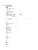
Exploded View and Replacement Parts List 1. Indoor Unit -57- 135312 135303 135314 249951 354210 135515 267110 268717 152312 268714-1 330870 144710-1 146811 144710-2 135500-3 146811 147581 352115 352116 35211B 352150 352380 263230 131410 146811 135500-2 135311-1 346810 349600 135311-2 - LG LSC121PMA | Service Manual - Page 58
152302 FILTER(MECH),A/C 249951 CONTROL BOX ASSEMBLY 263230 THERMISTOR ASSEMBLY 267110 REMOTE CONTROLLER ASSEMBLY 268712 PWB(PCB) ASSEMBLY,DISPLAY 268714-1 PWB(PCB) ASSEMBLY GUIDE 352150 HOSE ASSEMBLY,DRAIN 354210 EVAPORATOR ASSEMBLY,FIRST 359012 FAN,TURBO PART No. LSC091PMA LSC121PMA - LG LSC121PMA | Service Manual - Page 59
2. Outdoor unit(9K, 12K) -59- 554031 437210 546810 559010 649950 668711 261704 W0CZZ 430410 437212 435511 552111 552202 567502 554160 553000 550140 552203-1 561410 552116 552203-3 - LG LSC121PMA | Service Manual - Page 60
Parts List(outdoor) LOCATION No. DESCRIPTION 552203-1 VALVE,SERVICE 552203-3 VALVE,SERVICE 554031 CONDENSER ASSY,BENT 554160 COMPRESSOR SET 559010 FAN 550140 ISOLATOR, COMP PART No. LSC091PMA LSC121PMA 2H02479H 5220A20005B 2H01890L 5220A20003B 5403A20026D 5403A20019B 2520UKAC2HA - LG LSC121PMA | Service Manual - Page 61
MEMO -61- - LG LSC121PMA | Service Manual - Page 62
MEMO -62- - LG LSC121PMA | Service Manual - Page 63
P/No.: 3828A20135N July, 2003 Printed in Korea
-
 1
1 -
 2
2 -
 3
3 -
 4
4 -
 5
5 -
 6
6 -
 7
7 -
8
-
9
-
10
-
11
-
12
-
13
-
14
-
15
-
16
-
17
-
18
-
19
-
20
-
21
-
22
-
23
-
24
-
25
-
26
-
27
-
28
-
29
-
30
-
31
-
32
-
33
-
34
-
35
-
36
-
37
-
38
-
39
-
40
-
41
-
42
-
43
-
44
-
45
-
46
-
47
-
48
-
49
-
50
-
51
-
52
-
53
-
54
-
55
-
56
-
57
-
58
-
59
-
60
-
61
-
62
-
63
 |
 |

SERVICE MANUAL
Room Air Conditioner
MODEL : LSC091PMA
LSC121PMA