LG LSC121PMA Service Manual - Page 22
the indoor unit pipe insulation material. Bind them
 |
View all LG LSC121PMA manuals
Add to My Manuals
Save this manual to your list of manuals |
Page 22 highlights
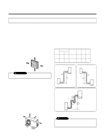
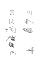
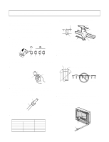
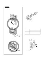
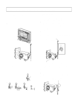
2. Tape the tubing, drain hose and the connecting cable. Be sure that the drain hose is located at the lowest side of the bundle. Locating at the upper side can cause drain pan to overflow inside the unit. s When extending the drain hose at the indoor unit, install the drain pipe. Drain pipe Connecting cable Drain hose Loop Gas side piping Liquid side piping Indoor unit drain hose Adhesive Vinyl tape(narrow) 4. Wrap the insulation material around the connecting portion. s Overlap the connection pipe insulation material and the indoor unit pipe insulation material. Bind them together with vinyl tape so that there is no gap. NOTE: If the drain hose is routed inside the room, insulate the hose with an insulation material* so that dripping from "sweating"(condensation) will not damage furniture or floors. *Foamed polyethylene or equivalent is recommended. 3. Connecting the pipings to the in door unit and drain hose to drain pipe s Align the center of the pipings and sufficiently tighten the flare nut by hand. Plastic bands Insulation material s Wrap the area which accommodates the rear piping housing section with vinyl tape. Connection pipe Vinyl tape (wide) Indoor unit pipe Wrap with vinyl tape Indoor unit tubing Flare nut Pipings s Tighten the flare nut with a wrench. Connecting cable Pipe Vinyl tape(narrow) Torque wrench Indoor unit tubing Spanner (fixed) Flare nut Connection pipe Capacity (Btu/h) 9K 12K Pipe Size[Torque] GAS LIQUID 1/2"[5.5kg.m] 1/4"[1.8kg.m] 1/2"[5.5kg.m] 1/4"[1.8kg.m] s Bundle the piping and drain hose together by wrapping them with vinyl tape over the range within which they fit into the rear piping housing section. Wrap with vinyl tape Pipe -22- Drain hose Vinyl tape(wide)
-
 1
1 -
2
-
3
-
4
-
5
-
6
-
7
-
8
-
9
-
10
-
11
-
12
-
13
-
14
-
15
-
16
-
 17
17 -
 18
18 -
 19
19 -
 20
20 -
 21
21 -
 22
22 -
 23
23 -
 24
24 -
 25
25 -
 26
26 -
 27
27 -
28
-
29
-
30
-
31
-
32
-
33
-
34
-
35
-
36
-
37
-
38
-
39
-
40
-
41
-
42
-
43
-
44
-
45
-
46
-
47
-
48
-
49
-
50
-
51
-
52
-
53
-
54
-
55
-
56
-
57
-
58
-
59
-
60
-
61
-
62
-
63
 |
 |
