LG LSC121PMA Service Manual - Page 9
Refrigeration Cycle Diagram
 |
View all LG LSC121PMA manuals
Add to My Manuals
Save this manual to your list of manuals |
Page 9 highlights
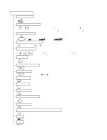
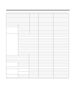
Refrigeration Cycle Diagram • Cooling Only Models INDOOR UNIT OUTDOOR UNIT LIQUID SIDE CAPILLARY TUBE HEAT EXCHANGER (EVAPORATOR) GAS SIDE HEAT EXCHANGER (CONDENSER) COMPRESSOR MODEL 9K, 12K (Cooling Only) Pipe size(Diameter:ø) Gas Liquid 1/2" 1/4" Piping length Rated Max 7.62m(25ft) 15m(50ft) Elevation Rated Max 5m(16ft) 7m(23ft) For installation over rated, *a proper quantity of refrigerant should be added for each meter. a proper quantity of refrigerant 9K, 12K 20g Ex) 9K: When installed at a distance of 15m, 148g of refrigerant should be added. (15-7.62) x 20g = 148g -9-
-
 1
1 -
2
-
3
-
 4
4 -
 5
5 -
 6
6 -
 7
7 -
 8
8 -
 9
9 -
 10
10 -
 11
11 -
 12
12 -
 13
13 -
 14
14 -
15
-
16
-
17
-
18
-
19
-
20
-
21
-
22
-
23
-
24
-
25
-
26
-
27
-
28
-
29
-
30
-
31
-
32
-
33
-
34
-
35
-
36
-
37
-
38
-
39
-
40
-
41
-
42
-
43
-
44
-
45
-
46
-
47
-
48
-
49
-
50
-
51
-
52
-
53
-
54
-
55
-
56
-
57
-
58
-
59
-
60
-
61
-
62
-
63
 |
 |
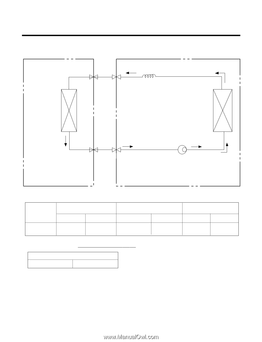
Refrigeration Cycle Diagram
-9-
For installation over rated, *a proper quantity of refr
iger
ant
should be added for each meter.
Ex) 9K: When installed at a distance of 15m, 148g of
refrigerant should be added.
(15-7.62) x 20g = 148g
INDOOR UNIT
HEAT
EXCHANGER
(EVAPORATOR)
HEAT
EXCHANGER
(CONDENSER)
COMPRESSOR
GAS SIDE
CAPILLARY TUBE
LIQUID SIDE
OUTDOOR UNIT
• Cooling Only Models
MODEL
9K, 12K
(Cooling Only)
Pipe size(Diameter:ø)
Piping length
Elevation
Gas
Liquid
Rated
Max
Rated
Max
1/2"
1/4"
7.62m(25ft)
15m(50ft)
5m(16ft)
7m(23ft)
a proper quantity of refrigerant
9K, 12K
20g