Lenovo J110 Hardware Maintenance Manual - Page 103
Machine Types 7396
 |
View all Lenovo J110 manuals
Add to My Manuals
Save this manual to your list of manuals |
Page 103 highlights
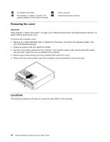
10 CMOS battery 20 12V power connector Machine Types 7396, 7397, and 7398 1 Microprocessor and heat sink 2 Microprocessor fan connector 3 Memory connector 1 4 Memory connector 2 5 Power connector 6 Diskette drive connector 7 IDE connector 8 SATA IDE connectors (2) 9 Front panel (power switch/LED) connector 10 Clear CMOS/Recovery jumper 11 Front USB connectors (2) 12 Serial (COM2) connector 13 Front audio connectors 14 PCI adapter connectors (2) 15 PCI Express x1 graphics adapter connector 16 CMOS battery 17 PCI Express x16 graphics adapter connector 18 System fan connector 19 12V power connector Removing and replacing the drive bay assembly You will need to remove the drive bay assembly to access some FRUs. 1. Remove the computer cover. See "Removing the cover" on page 94. 2. Remove the front bezel by releasing the three tabs and pivoting the top of the bezel outward. Chapter 9. Replacing FRUs (Types 7390, 7391, 7392, 7396, 7397, and 7398) 97
-
 1
1 -
2
-
3
-
4
-
5
-
6
-
7
-
8
-
9
-
10
-
11
-
12
-
13
-
14
-
15
-
16
-
17
-
18
-
19
-
20
-
21
-
22
-
23
-
24
-
25
-
26
-
27
-
28
-
29
-
30
-
31
-
32
-
33
-
34
-
35
-
36
-
37
-
38
-
39
-
40
-
41
-
42
-
43
-
44
-
45
-
46
-
47
-
48
-
49
-
50
-
51
-
52
-
53
-
54
-
55
-
56
-
57
-
58
-
59
-
60
-
61
-
62
-
63
-
64
-
65
-
66
-
67
-
68
-
69
-
70
-
71
-
72
-
73
-
74
-
75
-
76
-
77
-
78
-
79
-
80
-
81
-
82
-
83
-
84
-
85
-
86
-
87
-
88
-
89
-
90
-
91
-
92
-
93
-
94
-
95
-
96
-
97
-
 98
98 -
 99
99 -
 100
100 -
 101
101 -
 102
102 -
 103
103 -
 104
104 -
 105
105 -
 106
106 -
 107
107 -
 108
108 -
109
-
110
-
111
-
112
-
113
-
114
-
115
-
116
-
117
-
118
-
119
-
120
-
121
-
122
-
123
-
124
-
125
-
126
-
127
-
128
-
129
-
130
-
131
-
132
-
133
-
134
-
135
-
136
-
137
-
138
-
139
-
140
-
141
-
142
-
143
-
144
-
145
-
146
-
147
-
148
-
149
-
150
-
151
-
152
-
153
-
154
-
155
-
156
-
157
-
158
-
159
-
160
-
161
-
162
-
163
-
164
-
165
-
166
-
167
-
168
-
169
-
170
-
171
-
172
-
173
-
174
-
175
-
176
-
177
-
178
-
179
-
180
-
181
-
182
-
183
-
184
-
185
-
186
-
187
-
188
-
189
-
190
-
191
-
192
-
193
-
194
-
195
-
196
-
197
-
198
-
199
-
200
 |
 |
