Lenovo J110 Hardware Maintenance Manual - Page 91
Replacing the microprocessor (Types 7387, 7388, and 7389
 |
View all Lenovo J110 manuals
Add to My Manuals
Save this manual to your list of manuals |
Page 91 highlights
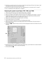
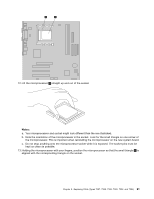
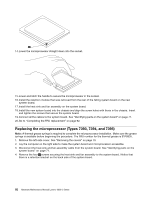
11. Lock the retainer with the small handle to secure the microprocessor in the socket. 12. Use the thermal grease syringe to place five drops of grease on the top of the microprocessor. Each drop of grease should be 0.03ml (3 tick marks on the grease syringe). 13. Install the heat sink and fan assembly on the system board. 14. Connect the heat sink and fan assembly cable to the system board. See "Identifying parts on the system board" on page 71 . 15. Go to "Completing the FRU replacement" on page 92. Replacing the microprocessor (Types 7387, 7388, and 7389) 1. Remove the left-side cover. See "Removing the covers" on page 70. 2. Lay the computer on the right side to make the system board and microprocessor accessible. 3. Disconnect the heat sink and fan assembly cable from the system board. See "Identifying parts on the system board" on page 71. 4. Rotate handle 1 to release the heat sink clamp and then disengage the clamp from the plastic retention bracket. Chapter 8. Replacing FRUs (Types 7387, 7388, 7389, 7393, 7394, and 7395) 85
-
 1
1 -
2
-
3
-
4
-
5
-
6
-
7
-
8
-
9
-
10
-
11
-
12
-
13
-
14
-
15
-
16
-
17
-
18
-
19
-
20
-
21
-
22
-
23
-
24
-
25
-
26
-
27
-
28
-
29
-
30
-
31
-
32
-
33
-
34
-
35
-
36
-
37
-
38
-
39
-
40
-
41
-
42
-
43
-
44
-
45
-
46
-
47
-
48
-
49
-
50
-
51
-
52
-
53
-
54
-
55
-
56
-
57
-
58
-
59
-
60
-
61
-
62
-
63
-
64
-
65
-
66
-
67
-
68
-
69
-
70
-
71
-
72
-
73
-
74
-
75
-
76
-
77
-
78
-
79
-
80
-
81
-
82
-
83
-
84
-
85
-
 86
86 -
 87
87 -
 88
88 -
 89
89 -
 90
90 -
 91
91 -
 92
92 -
 93
93 -
 94
94 -
 95
95 -
 96
96 -
97
-
98
-
99
-
100
-
101
-
102
-
103
-
104
-
105
-
106
-
107
-
108
-
109
-
110
-
111
-
112
-
113
-
114
-
115
-
116
-
117
-
118
-
119
-
120
-
121
-
122
-
123
-
124
-
125
-
126
-
127
-
128
-
129
-
130
-
131
-
132
-
133
-
134
-
135
-
136
-
137
-
138
-
139
-
140
-
141
-
142
-
143
-
144
-
145
-
146
-
147
-
148
-
149
-
150
-
151
-
152
-
153
-
154
-
155
-
156
-
157
-
158
-
159
-
160
-
161
-
162
-
163
-
164
-
165
-
166
-
167
-
168
-
169
-
170
-
171
-
172
-
173
-
174
-
175
-
176
-
177
-
178
-
179
-
180
-
181
-
182
-
183
-
184
-
185
-
186
-
187
-
188
-
189
-
190
-
191
-
192
-
193
-
194
-
195
-
196
-
197
-
198
-
199
-
200
 |
 |
