Lenovo J110 Hardware Maintenance Manual - Page 114
Replacing the microprocessor (Types 7396
 |
View all Lenovo J110 manuals
Add to My Manuals
Save this manual to your list of manuals |
Page 114 highlights
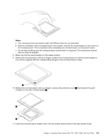
22. Install the new system board into the chassis and align the screw holes with those in the chassis. Insert and tighten the screws that secure the system board. 23. Connect all cables to the system board. See "Identifying parts on the system board" on page 95. 24. Replace the hard disk drive. See "Replacing the hard disk drive" on page 114. 25. Install the drive bay assembly and connect the power and signal cables to the drives. 26. Reinstall any PCI adapter cards that were removed. See "Replacing a PCI adapter" on page 99. 27. Position the fan duct on the heat sink fan. 28. Go to "Completing the FRU replacement" on page 117. Replacing the microprocessor (Types 7396, 7397, and 7398) Note: A thermal grease syringe is required to complete the microprocessor installation. Make sure the grease syringe is available before beginning the procedure. The FRU number for the thermal grease is 91P8835. 1. Remove the cover. See "Removing the cover" on page 94. 2. Lay the computer on the right side to make the system board and microprocessor accessible. 3. Disconnect the heat sink and fan assembly cable from the system board. See "Identifying parts on the system board" on page 71. 4. Remove the four screws securing the heat sink and fan assembly to the system board. Notice that there is a retention bracket on the back side of the system board. 5. Lift the heat sink and fan assembly off the failing system board. 6. Lift the small handle 3 and open the retainer 1 . 108 Hardware Maintenance Manual Lenovo 3000 J Series
-
 1
1 -
2
-
3
-
4
-
5
-
6
-
7
-
8
-
9
-
10
-
11
-
12
-
13
-
14
-
15
-
16
-
17
-
18
-
19
-
20
-
21
-
22
-
23
-
24
-
25
-
26
-
27
-
28
-
29
-
30
-
31
-
32
-
33
-
34
-
35
-
36
-
37
-
38
-
39
-
40
-
41
-
42
-
43
-
44
-
45
-
46
-
47
-
48
-
49
-
50
-
51
-
52
-
53
-
54
-
55
-
56
-
57
-
58
-
59
-
60
-
61
-
62
-
63
-
64
-
65
-
66
-
67
-
68
-
69
-
70
-
71
-
72
-
73
-
74
-
75
-
76
-
77
-
78
-
79
-
80
-
81
-
82
-
83
-
84
-
85
-
86
-
87
-
88
-
89
-
90
-
91
-
92
-
93
-
94
-
95
-
96
-
97
-
98
-
99
-
100
-
101
-
102
-
103
-
104
-
105
-
106
-
107
-
108
-
 109
109 -
 110
110 -
 111
111 -
 112
112 -
 113
113 -
 114
114 -
 115
115 -
 116
116 -
 117
117 -
 118
118 -
 119
119 -
120
-
121
-
122
-
123
-
124
-
125
-
126
-
127
-
128
-
129
-
130
-
131
-
132
-
133
-
134
-
135
-
136
-
137
-
138
-
139
-
140
-
141
-
142
-
143
-
144
-
145
-
146
-
147
-
148
-
149
-
150
-
151
-
152
-
153
-
154
-
155
-
156
-
157
-
158
-
159
-
160
-
161
-
162
-
163
-
164
-
165
-
166
-
167
-
168
-
169
-
170
-
171
-
172
-
173
-
174
-
175
-
176
-
177
-
178
-
179
-
180
-
181
-
182
-
183
-
184
-
185
-
186
-
187
-
188
-
189
-
190
-
191
-
192
-
193
-
194
-
195
-
196
-
197
-
198
-
199
-
200
 |
 |
