Lenovo J110 Hardware Maintenance Manual - Page 86
Replacing the system board (Types 7387
 |
View all Lenovo J110 manuals
Add to My Manuals
Save this manual to your list of manuals |
Page 86 highlights
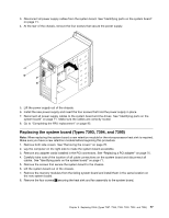
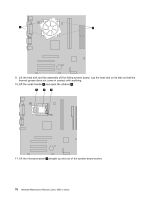
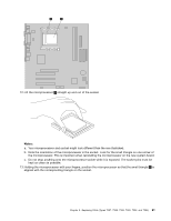
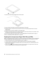
19. Install the new system board into the chassis and align the screw holes with those in the chassis. Insert and tighten the screws that secure the system board. 20. Connect all the cables to the system board. See "Identifying parts on the system board" on page 71. 21. Go to "Completing the FRU replacement" on page 92. Replacing the system board (Types 7387, 7388, and 7389) 1. Remove only the left-side cover. See "Removing the covers" on page 70. 2. Lay the computer on the right side to make the system board accessible. 3. Remove any adapter cards installed in the PCI connectors. See "Replacing a PCI adapter" on page 75. 4. Carefully take note of the location of all cable connections on the system board and disconnect all cables. See "Identifying parts on the system board" on page 71. 5. Remove the screws that secure the system board to the chassis. 6. Lift the system board out of the chassis. 7. Remove the retention module from the rear of the failing system board. 8. Remove the memory modules from the failing system board and install them in the same location on the new system board. 9. Rotate handle 1 to release the heat sink clamp and then disengage the clamp from the heat sink and fan assembly. 10. Lift the heat sink and fan assembly off the failing system board. Lay the heat sink on its side so that the thermal grease does not come in contact with anything. 11. Lift the small handle 1 . 80 Hardware Maintenance Manual Lenovo 3000 J Series
-
 1
1 -
2
-
3
-
4
-
5
-
6
-
7
-
8
-
9
-
10
-
11
-
12
-
13
-
14
-
15
-
16
-
17
-
18
-
19
-
20
-
21
-
22
-
23
-
24
-
25
-
26
-
27
-
28
-
29
-
30
-
31
-
32
-
33
-
34
-
35
-
36
-
37
-
38
-
39
-
40
-
41
-
42
-
43
-
44
-
45
-
46
-
47
-
48
-
49
-
50
-
51
-
52
-
53
-
54
-
55
-
56
-
57
-
58
-
59
-
60
-
61
-
62
-
63
-
64
-
65
-
66
-
67
-
68
-
69
-
70
-
71
-
72
-
73
-
74
-
75
-
76
-
77
-
78
-
79
-
80
-
 81
81 -
 82
82 -
 83
83 -
 84
84 -
 85
85 -
 86
86 -
 87
87 -
 88
88 -
 89
89 -
 90
90 -
 91
91 -
92
-
93
-
94
-
95
-
96
-
97
-
98
-
99
-
100
-
101
-
102
-
103
-
104
-
105
-
106
-
107
-
108
-
109
-
110
-
111
-
112
-
113
-
114
-
115
-
116
-
117
-
118
-
119
-
120
-
121
-
122
-
123
-
124
-
125
-
126
-
127
-
128
-
129
-
130
-
131
-
132
-
133
-
134
-
135
-
136
-
137
-
138
-
139
-
140
-
141
-
142
-
143
-
144
-
145
-
146
-
147
-
148
-
149
-
150
-
151
-
152
-
153
-
154
-
155
-
156
-
157
-
158
-
159
-
160
-
161
-
162
-
163
-
164
-
165
-
166
-
167
-
168
-
169
-
170
-
171
-
172
-
173
-
174
-
175
-
176
-
177
-
178
-
179
-
180
-
181
-
182
-
183
-
184
-
185
-
186
-
187
-
188
-
189
-
190
-
191
-
192
-
193
-
194
-
195
-
196
-
197
-
198
-
199
-
200
 |
 |
