Lenovo J110 Hardware Maintenance Manual - Page 105
Replacing a PCI adapter, Go to Completing the FRU replacement
 |
View all Lenovo J110 manuals
Add to My Manuals
Save this manual to your list of manuals |
Page 105 highlights
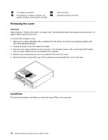
2. Remove the drive bay assembly. See "Removing and replacing the drive bay assembly" on page 97. 3. Locate the memory connectors. See "Identifying parts on the system board" on page 95. 4. Open the retaining clips and remove the failing memory module. 5. Make sure the notch 1 on the new memory module is aligned correctly with the connector key 2 on the socket. Insert the memory module straight down into the connector until it snaps into position and the retaining clips are closed. 6. Replace the drive bay assembly. See "Removing and replacing the drive bay assembly" on page 97. 7. Go to "Completing the FRU replacement" on page 117. Replacing a PCI adapter 1. Remove the computer cover. See "Removing the cover" on page 94. 2. Remove the screw that secures the adapter retainer and remove the retainer. Chapter 9. Replacing FRUs (Types 7390, 7391, 7392, 7396, 7397, and 7398) 99
-
 1
1 -
2
-
3
-
4
-
5
-
6
-
7
-
8
-
9
-
10
-
11
-
12
-
13
-
14
-
15
-
16
-
17
-
18
-
19
-
20
-
21
-
22
-
23
-
24
-
25
-
26
-
27
-
28
-
29
-
30
-
31
-
32
-
33
-
34
-
35
-
36
-
37
-
38
-
39
-
40
-
41
-
42
-
43
-
44
-
45
-
46
-
47
-
48
-
49
-
50
-
51
-
52
-
53
-
54
-
55
-
56
-
57
-
58
-
59
-
60
-
61
-
62
-
63
-
64
-
65
-
66
-
67
-
68
-
69
-
70
-
71
-
72
-
73
-
74
-
75
-
76
-
77
-
78
-
79
-
80
-
81
-
82
-
83
-
84
-
85
-
86
-
87
-
88
-
89
-
90
-
91
-
92
-
93
-
94
-
95
-
96
-
97
-
98
-
99
-
 100
100 -
 101
101 -
 102
102 -
 103
103 -
 104
104 -
 105
105 -
 106
106 -
 107
107 -
 108
108 -
 109
109 -
 110
110 -
111
-
112
-
113
-
114
-
115
-
116
-
117
-
118
-
119
-
120
-
121
-
122
-
123
-
124
-
125
-
126
-
127
-
128
-
129
-
130
-
131
-
132
-
133
-
134
-
135
-
136
-
137
-
138
-
139
-
140
-
141
-
142
-
143
-
144
-
145
-
146
-
147
-
148
-
149
-
150
-
151
-
152
-
153
-
154
-
155
-
156
-
157
-
158
-
159
-
160
-
161
-
162
-
163
-
164
-
165
-
166
-
167
-
168
-
169
-
170
-
171
-
172
-
173
-
174
-
175
-
176
-
177
-
178
-
179
-
180
-
181
-
182
-
183
-
184
-
185
-
186
-
187
-
188
-
189
-
190
-
191
-
192
-
193
-
194
-
195
-
196
-
197
-
198
-
199
-
200
 |
 |
