Lenovo J110 Hardware Maintenance Manual - Page 79
Machine Types 7393
 |
View all Lenovo J110 manuals
Add to My Manuals
Save this manual to your list of manuals |
Page 79 highlights
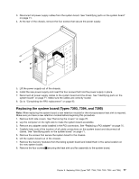
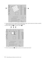
10 CMOS battery 20 12V power connector Machine Types 7393, 7394, and 7395 1 Microprocessor and heat sink 2 Microprocessor fan connector 3 Memory connector 1 4 Memory connector 2 5 Power connector 6 Diskette drive connector 7 IDE connector 8 SATA IDE connectors (2) 9 Front panel (power switch/LED) connector 10 Clear CMOS/Recovery jumper 11 Front USB connectors (2) 12 Serial (COM2) connector 13 Front audio connectors 14 PCI adapter connectors (2) 15 PCI Express x1 graphics adapter connector 16 CMOS battery 17 PCI Express x16 graphics adapter connector 18 System fan connector 19 12V power connector Removing and replacing the front bezel The front bezel must be removed to replace some FRUs. 1. Remove both the left-side and right-side covers. See "Removing the covers" on page 70. 2. Disconnect the cable for the power switch/LED assembly from the system board. See "Identifying parts on the system board" on page 71 for the connector location. 3. Remove the screws that secure the bezel. There are two on each side. Chapter 8. Replacing FRUs (Types 7387, 7388, 7389, 7393, 7394, and 7395) 73
-
 1
1 -
2
-
3
-
4
-
5
-
6
-
7
-
8
-
9
-
10
-
11
-
12
-
13
-
14
-
15
-
16
-
17
-
18
-
19
-
20
-
21
-
22
-
23
-
24
-
25
-
26
-
27
-
28
-
29
-
30
-
31
-
32
-
33
-
34
-
35
-
36
-
37
-
38
-
39
-
40
-
41
-
42
-
43
-
44
-
45
-
46
-
47
-
48
-
49
-
50
-
51
-
52
-
53
-
54
-
55
-
56
-
57
-
58
-
59
-
60
-
61
-
62
-
63
-
64
-
65
-
66
-
67
-
68
-
69
-
70
-
71
-
72
-
73
-
 74
74 -
 75
75 -
 76
76 -
 77
77 -
 78
78 -
 79
79 -
 80
80 -
 81
81 -
 82
82 -
 83
83 -
 84
84 -
85
-
86
-
87
-
88
-
89
-
90
-
91
-
92
-
93
-
94
-
95
-
96
-
97
-
98
-
99
-
100
-
101
-
102
-
103
-
104
-
105
-
106
-
107
-
108
-
109
-
110
-
111
-
112
-
113
-
114
-
115
-
116
-
117
-
118
-
119
-
120
-
121
-
122
-
123
-
124
-
125
-
126
-
127
-
128
-
129
-
130
-
131
-
132
-
133
-
134
-
135
-
136
-
137
-
138
-
139
-
140
-
141
-
142
-
143
-
144
-
145
-
146
-
147
-
148
-
149
-
150
-
151
-
152
-
153
-
154
-
155
-
156
-
157
-
158
-
159
-
160
-
161
-
162
-
163
-
164
-
165
-
166
-
167
-
168
-
169
-
170
-
171
-
172
-
173
-
174
-
175
-
176
-
177
-
178
-
179
-
180
-
181
-
182
-
183
-
184
-
185
-
186
-
187
-
188
-
189
-
190
-
191
-
192
-
193
-
194
-
195
-
196
-
197
-
198
-
199
-
200
 |
 |
