Lenovo ThinkCentre Edge 91 Hardware Maintenance Manual (HMM) (April 2012) - Th - Page 103
corresponding holes in the new system board. Carefully slide the new system board into the chassis until
 |
View all Lenovo ThinkCentre Edge 91 manuals
Add to My Manuals
Save this manual to your list of manuals |
Page 103 highlights
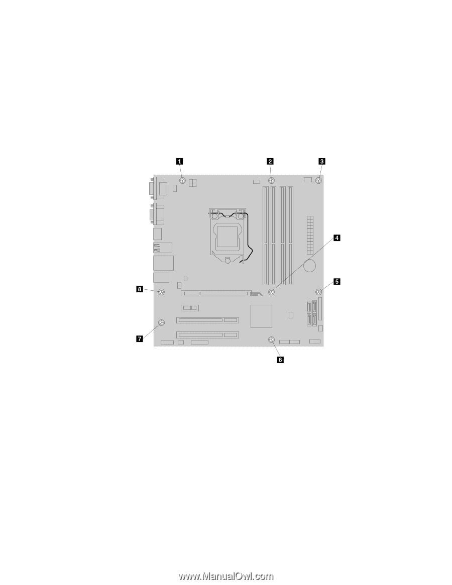
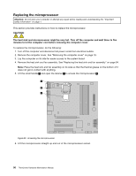
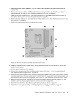
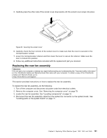
5. Remove the power supply assembly from the chassis. See "Replacing the power supply assembly" on page 92. 6. Remove all memory modules and PCI cards that are currently installed. See "Installing or replacing a memory module" on page 85 and "Installing or replacing a PCI card" on page 82. 7. Carefully take note of the locations of all cable connections on the system board and disconnect all the cables. See "Locating parts on the system board" on page 77. 8. Remove the heat sink and fan assembly from the failing system board. See "Replacing the heat sink and fan assembly" on page 94. 9. Remove the eight screws that secure the system board. Figure 28. Removing the eight screws that secure the system board 10. Carefully slide the system board so that it can be released from the mounting studs that secure the system board in place. 11. Lift the system board out of the chassis. 12. Remove the microprocessor from the failing system board and install it on the new system board. See "Replacing the microprocessor" on page 96. 13. Install the new system board into the chassis by aligning the eight mounting studs in the chassis with the corresponding holes in the new system board. Carefully slide the new system board into the chassis until it is secured in place by the mounting studs. Then, install the eight screws to secure the system board. 14. Install the heat sink and fan assembly and connect the heat sink and fan assembly cable to the new system board. See "Replacing the heat sink and fan assembly" on page 94. 15. Install the hard disk drive . See "Replacing the primary hard disk drive" on page 88. 16. Install the power supply assembly. See "Replacing the power supply assembly" on page 92. Chapter 8. Replacing FRUs (Machine Types: 1852, 1853, and 1855) 99
-
 1
1 -
2
-
3
-
4
-
5
-
6
-
7
-
8
-
9
-
10
-
11
-
12
-
13
-
14
-
15
-
16
-
17
-
18
-
19
-
20
-
21
-
22
-
23
-
24
-
25
-
26
-
27
-
28
-
29
-
30
-
31
-
32
-
33
-
34
-
35
-
36
-
37
-
38
-
39
-
40
-
41
-
42
-
43
-
44
-
45
-
46
-
47
-
48
-
49
-
50
-
51
-
52
-
53
-
54
-
55
-
56
-
57
-
58
-
59
-
60
-
61
-
62
-
63
-
64
-
65
-
66
-
67
-
68
-
69
-
70
-
71
-
72
-
73
-
74
-
75
-
76
-
77
-
78
-
79
-
80
-
81
-
82
-
83
-
84
-
85
-
86
-
87
-
88
-
89
-
90
-
91
-
92
-
93
-
94
-
95
-
96
-
97
-
 98
98 -
 99
99 -
 100
100 -
 101
101 -
 102
102 -
 103
103 -
 104
104 -
 105
105 -
 106
106 -
 107
107 -
 108
108 -
109
-
110
-
111
-
112
-
113
-
114
-
115
-
116
-
117
-
118
-
119
-
120
-
121
-
122
-
123
-
124
-
125
-
126
-
127
-
128
-
129
-
130
-
131
-
132
-
133
-
134
-
135
-
136
-
137
-
138
-
139
-
140
-
141
-
142
-
143
-
144
-
145
-
146
-
147
-
148
-
149
-
150
-
151
-
152
-
153
-
154
-
155
-
156
-
157
-
158
-
159
-
160
-
161
-
162
-
163
-
164
-
165
-
166
-
167
-
168
-
169
-
170
-
171
-
172
-
173
-
174
-
175
-
176
-
177
-
178
-
179
-
180
-
181
-
182
-
183
-
184
-
185
-
186
-
187
-
188
-
189
-
190
-
191
-
192
-
193
-
194
-
195
-
196
-
197
-
198
-
199
-
200
-
201
-
202
-
203
-
204
-
205
-
206
-
207
-
208
-
209
-
210
-
211
-
212
-
213
-
214
-
215
-
216
-
217
-
218
-
219
-
220
-
221
-
222
-
223
-
224
-
225
-
226
-
227
-
228
-
229
-
230
-
231
-
232
-
233
-
234
-
235
-
236
-
237
-
238
-
239
-
240
-
241
-
242
-
243
-
244
-
245
-
246
-
247
-
248
-
249
-
250
-
251
-
252
-
253
-
254
-
255
-
256
-
257
-
258
-
259
-
260
-
261
-
262
 |
 |