Lenovo ThinkCentre Edge 91 Hardware Maintenance Manual (HMM) (April 2012) - Th - Page 108
Completing the parts replacement
 |
View all Lenovo ThinkCentre Edge 91 manuals
Add to My Manuals
Save this manual to your list of manuals |
Page 108 highlights
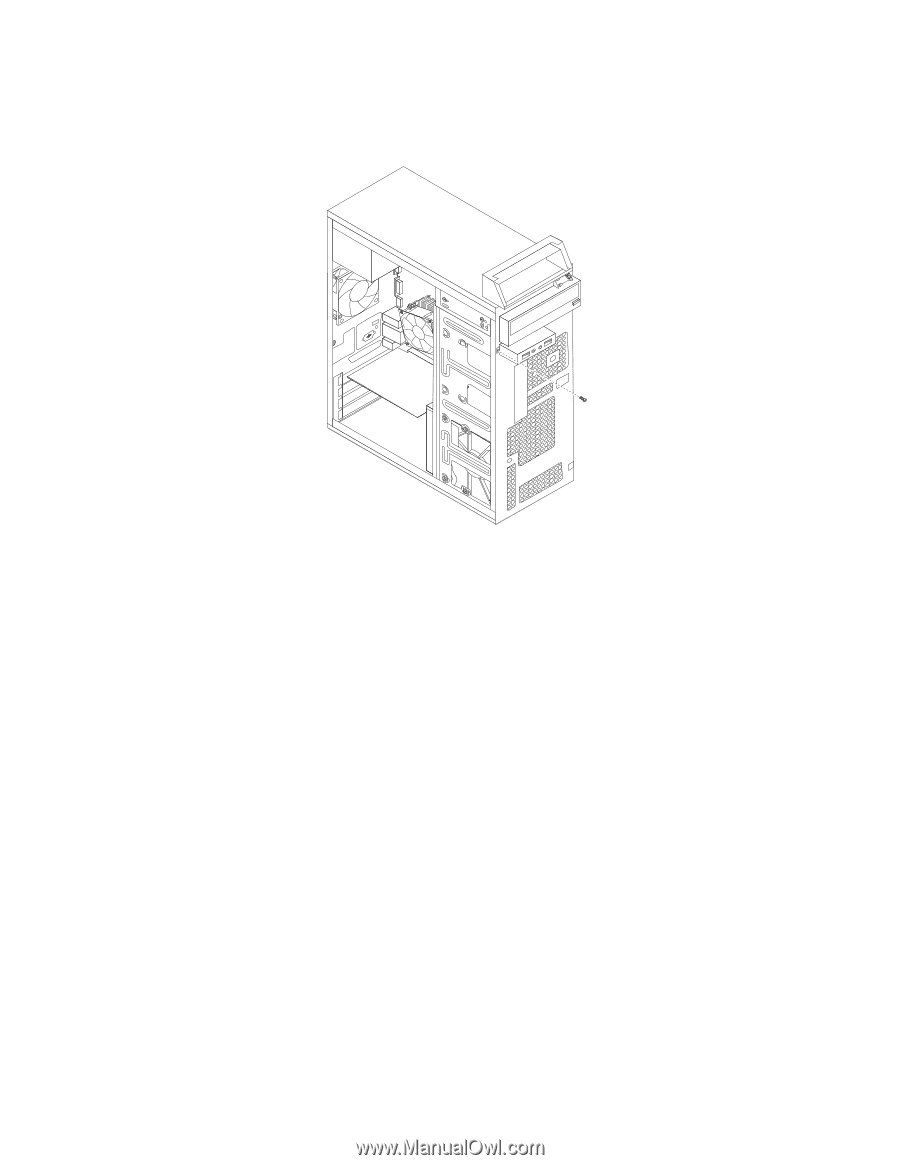
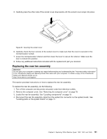
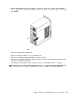
6. Remove the screw that secures the front audio and USB assembly bracket to the chassis to remove the bracket from the chassis. Figure 33. Removing the front audio and USB assembly 7. Install the new front audio and USB assembly into the chassis and align the screw hole in the bracket with the corresponding hole in the chassis. 8. Install the screw to secure the new front audio and USB assembly to the chassis. 9. Reconnect the front audio and USB assembly cables to the front audio connector and the front USB connector on the system board. See "Locating parts on the system board" on page 77. 10. To complete the installation or replacement, go to "Completing the parts replacement" on page 104. Completing the parts replacement After completing the installation or replacement for all parts, you need to reinstall the computer cover and reconnect cables. Depending on the parts you installed or replaced, you might need to confirm the updated information in the Setup Utility program. Refer to Chapter 6 "Using the Setup Utility program" on page 43. To reinstall the computer cover and reconnect cables to your computer, do the following: 1. Make sure that all components have been reassembled correctly and that no tools or loose screws are left inside your computer. See "Locating components" on page 76 for the locations of various components in your computer. 2. Make sure that the cables are routed correctly. Keep cables clear of the hinges and sides of the computer chassis to avoid interference with closing the computer cover. 3. If you have removed the front bezel, reinstall it. See "Removing and reinstalling the front bezel" on page 80. 104 ThinkCentre Hardware Maintenance Manual
-
 1
1 -
2
-
3
-
4
-
5
-
6
-
7
-
8
-
9
-
10
-
11
-
12
-
13
-
14
-
15
-
16
-
17
-
18
-
19
-
20
-
21
-
22
-
23
-
24
-
25
-
26
-
27
-
28
-
29
-
30
-
31
-
32
-
33
-
34
-
35
-
36
-
37
-
38
-
39
-
40
-
41
-
42
-
43
-
44
-
45
-
46
-
47
-
48
-
49
-
50
-
51
-
52
-
53
-
54
-
55
-
56
-
57
-
58
-
59
-
60
-
61
-
62
-
63
-
64
-
65
-
66
-
67
-
68
-
69
-
70
-
71
-
72
-
73
-
74
-
75
-
76
-
77
-
78
-
79
-
80
-
81
-
82
-
83
-
84
-
85
-
86
-
87
-
88
-
89
-
90
-
91
-
92
-
93
-
94
-
95
-
96
-
97
-
98
-
99
-
100
-
101
-
102
-
 103
103 -
 104
104 -
 105
105 -
 106
106 -
 107
107 -
 108
108 -
 109
109 -
 110
110 -
 111
111 -
 112
112 -
 113
113 -
114
-
115
-
116
-
117
-
118
-
119
-
120
-
121
-
122
-
123
-
124
-
125
-
126
-
127
-
128
-
129
-
130
-
131
-
132
-
133
-
134
-
135
-
136
-
137
-
138
-
139
-
140
-
141
-
142
-
143
-
144
-
145
-
146
-
147
-
148
-
149
-
150
-
151
-
152
-
153
-
154
-
155
-
156
-
157
-
158
-
159
-
160
-
161
-
162
-
163
-
164
-
165
-
166
-
167
-
168
-
169
-
170
-
171
-
172
-
173
-
174
-
175
-
176
-
177
-
178
-
179
-
180
-
181
-
182
-
183
-
184
-
185
-
186
-
187
-
188
-
189
-
190
-
191
-
192
-
193
-
194
-
195
-
196
-
197
-
198
-
199
-
200
-
201
-
202
-
203
-
204
-
205
-
206
-
207
-
208
-
209
-
210
-
211
-
212
-
213
-
214
-
215
-
216
-
217
-
218
-
219
-
220
-
221
-
222
-
223
-
224
-
225
-
226
-
227
-
228
-
229
-
230
-
231
-
232
-
233
-
234
-
235
-
236
-
237
-
238
-
239
-
240
-
241
-
242
-
243
-
244
-
245
-
246
-
247
-
248
-
249
-
250
-
251
-
252
-
253
-
254
-
255
-
256
-
257
-
258
-
259
-
260
-
261
-
262
 |
 |