Lenovo ThinkCentre Edge 91 Hardware Maintenance Manual (HMM) (April 2012) - Th - Page 111
Replacing FRUs (Machine Types: 1857
 |
View all Lenovo ThinkCentre Edge 91 manuals
Add to My Manuals
Save this manual to your list of manuals |
Page 111 highlights
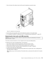
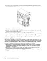
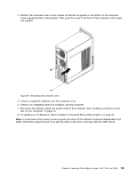
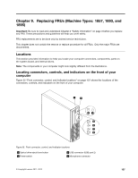
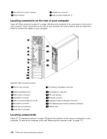
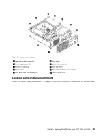
Chapter 9. Replacing FRUs (Machine Types: 1857, 1893, and 1895) Important: Be sure to read and understand Chapter 2 "Safety information" on page 3 before you replace any FRU. These precautions and guidelines will help you work safely. FRU replacements are to be done only by trained service technicians. This chapter does not contain the remove or replace procedure for all FRUs. Only the major FRUs are documented. Locations This section provides information to help you locate your computer connectors, components, parts on the system board, and internal drives. Note: The components in your computer might look slightly different from the illustrations. Locating connectors, controls, and indicators on the front of your computer Figure 35 "Front connector, control, and indicator locations" on page 107 shows the locations of the connectors, controls, and indicators on the front of your computer. Figure 35. Front connector, control, and indicator locations 1 Optical drive eject/close button 2 Power switch 5 USB connector (USB port 2) 6 Microphone connector © Copyright Lenovo 2011, 2012 107
-
 1
1 -
2
-
3
-
4
-
5
-
6
-
7
-
8
-
9
-
10
-
11
-
12
-
13
-
14
-
15
-
16
-
17
-
18
-
19
-
20
-
21
-
22
-
23
-
24
-
25
-
26
-
27
-
28
-
29
-
30
-
31
-
32
-
33
-
34
-
35
-
36
-
37
-
38
-
39
-
40
-
41
-
42
-
43
-
44
-
45
-
46
-
47
-
48
-
49
-
50
-
51
-
52
-
53
-
54
-
55
-
56
-
57
-
58
-
59
-
60
-
61
-
62
-
63
-
64
-
65
-
66
-
67
-
68
-
69
-
70
-
71
-
72
-
73
-
74
-
75
-
76
-
77
-
78
-
79
-
80
-
81
-
82
-
83
-
84
-
85
-
86
-
87
-
88
-
89
-
90
-
91
-
92
-
93
-
94
-
95
-
96
-
97
-
98
-
99
-
100
-
101
-
102
-
103
-
104
-
105
-
 106
106 -
 107
107 -
 108
108 -
 109
109 -
 110
110 -
 111
111 -
 112
112 -
 113
113 -
 114
114 -
 115
115 -
 116
116 -
117
-
118
-
119
-
120
-
121
-
122
-
123
-
124
-
125
-
126
-
127
-
128
-
129
-
130
-
131
-
132
-
133
-
134
-
135
-
136
-
137
-
138
-
139
-
140
-
141
-
142
-
143
-
144
-
145
-
146
-
147
-
148
-
149
-
150
-
151
-
152
-
153
-
154
-
155
-
156
-
157
-
158
-
159
-
160
-
161
-
162
-
163
-
164
-
165
-
166
-
167
-
168
-
169
-
170
-
171
-
172
-
173
-
174
-
175
-
176
-
177
-
178
-
179
-
180
-
181
-
182
-
183
-
184
-
185
-
186
-
187
-
188
-
189
-
190
-
191
-
192
-
193
-
194
-
195
-
196
-
197
-
198
-
199
-
200
-
201
-
202
-
203
-
204
-
205
-
206
-
207
-
208
-
209
-
210
-
211
-
212
-
213
-
214
-
215
-
216
-
217
-
218
-
219
-
220
-
221
-
222
-
223
-
224
-
225
-
226
-
227
-
228
-
229
-
230
-
231
-
232
-
233
-
234
-
235
-
236
-
237
-
238
-
239
-
240
-
241
-
242
-
243
-
244
-
245
-
246
-
247
-
248
-
249
-
250
-
251
-
252
-
253
-
254
-
255
-
256
-
257
-
258
-
259
-
260
-
261
-
262
 |
 |