Lenovo ThinkPad Edge E135 Hardware Maintenance Manual - Page 76
System board assembly, 1050 PCI Express Mini Card for wireless LAN
 |
View all Lenovo ThinkPad Edge E135 manuals
Add to My Manuals
Save this manual to your list of manuals |
Page 76 highlights
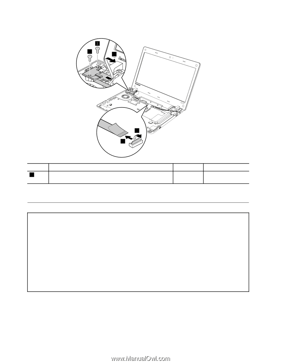
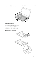
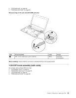
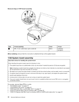
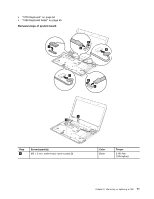
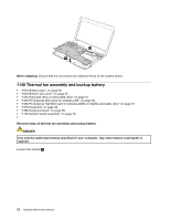
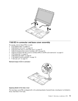
Removal steps of CRT board assembly 23 3 4 1 2 Step 3 Screw (quantity) M2 × 3 mm, wafer-head, nylon-coated (2) Color Black Torque 0.392 Nm (4 kgfcm) When installing: Ensure that the connector is attached firmly to the system board. 1130 System board assembly Important notices for handling the system board: When handling the system board, bear the following in mind: • The system board has an accelerometer, which can be broken if several thousands of G-forces are applied. Note: Dropping a system board from a height of as little as six inches so that it falls flat on a hard bench can subject the accelerometer to as much as 6,000 G's of shock. • Be careful not to drop the system board on a bench top that has a hard surface, such as metal, wood, or composite. • If a system board is dropped, be sure to document the drop in any reject report, and replace the system board. • Avoid rough handling of any kind. • At every point in the process, be sure not to drop or stack the system board. • If you put a system board down, be sure to put it only on a padded surface such as an ESD mat or a corrugated conductive surface. For access, remove these FRUs in order: • "1010 Battery pack" on page 54 • "1020 Bottom slot cover" on page 55 • "1040 Hard disk drive or solid-state drive" on page 57 • "1050 PCI Express Mini Card for wireless LAN" on page 59 • "1060 PCI Express Half Mini Card for wireless WAN or mSATA solid-state drive" on page 61 70 Hardware Maintenance Manual
-
 1
1 -
2
-
3
-
4
-
5
-
6
-
7
-
8
-
9
-
10
-
11
-
12
-
13
-
14
-
15
-
16
-
17
-
18
-
19
-
20
-
21
-
22
-
23
-
24
-
25
-
26
-
27
-
28
-
29
-
30
-
31
-
32
-
33
-
34
-
35
-
36
-
37
-
38
-
39
-
40
-
41
-
42
-
43
-
44
-
45
-
46
-
47
-
48
-
49
-
50
-
51
-
52
-
53
-
54
-
55
-
56
-
57
-
58
-
59
-
60
-
61
-
62
-
63
-
64
-
65
-
66
-
67
-
68
-
69
-
70
-
 71
71 -
 72
72 -
 73
73 -
 74
74 -
 75
75 -
 76
76 -
 77
77 -
 78
78 -
 79
79 -
 80
80 -
 81
81 -
82
-
83
-
84
-
85
-
86
-
87
-
88
-
89
-
90
-
91
-
92
 |
 |