Lenovo ThinkPad Edge E135 Hardware Maintenance Manual - Page 85
Integrated camera
 |
View all Lenovo ThinkPad Edge E135 manuals
Add to My Manuals
Save this manual to your list of manuals |
Page 85 highlights
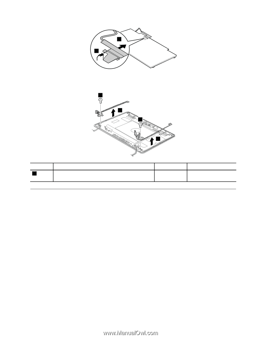
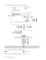
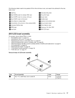
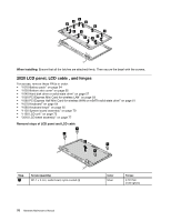
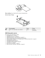
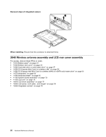
4 3 When installing: Ensure that the LCD connector is attached firmly. Removal steps of hinges 1 2 1 2 Step 1 Screw (quantity) M2.5 × 6 mm, wafer-head, nylon-coated (2) Color Silver Torque 0.181 Nm (1.85 kgfcm) 2030 Integrated camera For access, remove these FRUs in order: • "1010 Battery pack" on page 54 • "1020 Bottom slot cover" on page 55 • "1040 Hard disk drive or solid-state drive" on page 57 • "1050 PCI Express Mini Card for wireless LAN" on page 59 • "1060 PCI Express Half Mini Card for wireless WAN or mSATA solid-state drive" on page 61 • "1070 Keyboard" on page 64 • "1080 Keyboard bezel" on page 65 • "1130 System board assembly" on page 70 • "1150 LCD unit" on page 73 • "2010 LCD bezel assembly" on page 77 • "2020 LCD panel, LCD cable , and hinges" on page 78 Chapter 9. Removing or replacing a FRU 79
-
 1
1 -
2
-
3
-
4
-
5
-
6
-
7
-
8
-
9
-
10
-
11
-
12
-
13
-
14
-
15
-
16
-
17
-
18
-
19
-
20
-
21
-
22
-
23
-
24
-
25
-
26
-
27
-
28
-
29
-
30
-
31
-
32
-
33
-
34
-
35
-
36
-
37
-
38
-
39
-
40
-
41
-
42
-
43
-
44
-
45
-
46
-
47
-
48
-
49
-
50
-
51
-
52
-
53
-
54
-
55
-
56
-
57
-
58
-
59
-
60
-
61
-
62
-
63
-
64
-
65
-
66
-
67
-
68
-
69
-
70
-
71
-
72
-
73
-
74
-
75
-
76
-
77
-
78
-
79
-
 80
80 -
 81
81 -
 82
82 -
 83
83 -
 84
84 -
 85
85 -
 86
86 -
 87
87 -
 88
88 -
 89
89 -
 90
90 -
91
-
92
 |
 |