Lenovo ThinkPad Edge E135 Hardware Maintenance Manual - Page 87
Removal steps of wireless antenna assembly and LCD rear cover assembly, Cable routing
 |
View all Lenovo ThinkPad Edge E135 manuals
Add to My Manuals
Save this manual to your list of manuals |
Page 87 highlights
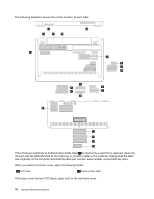
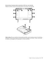
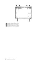
Removal steps of wireless antenna assembly and LCD rear cover assembly Release the antenna cables from the cable guides on the LCD rear cover assembly. 2 1 1 2 2 1 1 2 2 2 3 3 Cable routing: When you install the wireless antenna assembly, route the cables as shown in the following illustrations. As you route the cables, ensure that they are not subject to any tension. Tension could cause the cables to be damaged by the cable guides, or a wire to be broken. Chapter 9. Removing or replacing a FRU 81
-
 1
1 -
2
-
3
-
4
-
5
-
6
-
7
-
8
-
9
-
10
-
11
-
12
-
13
-
14
-
15
-
16
-
17
-
18
-
19
-
20
-
21
-
22
-
23
-
24
-
25
-
26
-
27
-
28
-
29
-
30
-
31
-
32
-
33
-
34
-
35
-
36
-
37
-
38
-
39
-
40
-
41
-
42
-
43
-
44
-
45
-
46
-
47
-
48
-
49
-
50
-
51
-
52
-
53
-
54
-
55
-
56
-
57
-
58
-
59
-
60
-
61
-
62
-
63
-
64
-
65
-
66
-
67
-
68
-
69
-
70
-
71
-
72
-
73
-
74
-
75
-
76
-
77
-
78
-
79
-
80
-
81
-
 82
82 -
 83
83 -
 84
84 -
 85
85 -
 86
86 -
 87
87 -
 88
88 -
 89
89 -
 90
90 -
 91
91 -
 92
92
 |
 |
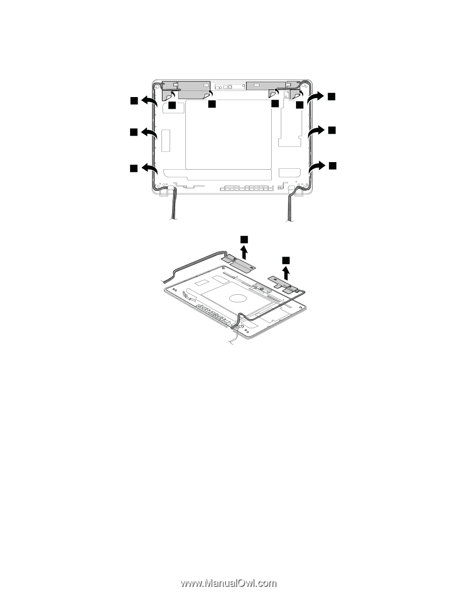
Removal steps of wireless antenna assembly and LCD rear cover assembly
Release the antenna cables from the cable guides on the LCD rear cover assembly.
1
1
1
1
2
2
2
2
2
2
3
3
Cable routing:
When you install the wireless antenna assembly, route the cables as shown in the following
illustrations. As you route the cables, ensure that they are not subject to any tension. Tension could cause
the cables to be damaged by the cable guides, or a wire to be broken.
Chapter 9
.
Removing or replacing a FRU
81