Lenovo ThinkPad L530 Hardware Maintenance Manual - Page 112
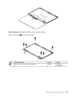
LCD panel, hinges, and LCD rear cover assembly, When installing, Removal steps of LCD panel
 |
View all Lenovo ThinkPad L530 manuals
Add to My Manuals
Save this manual to your list of manuals |
Page 112 highlights
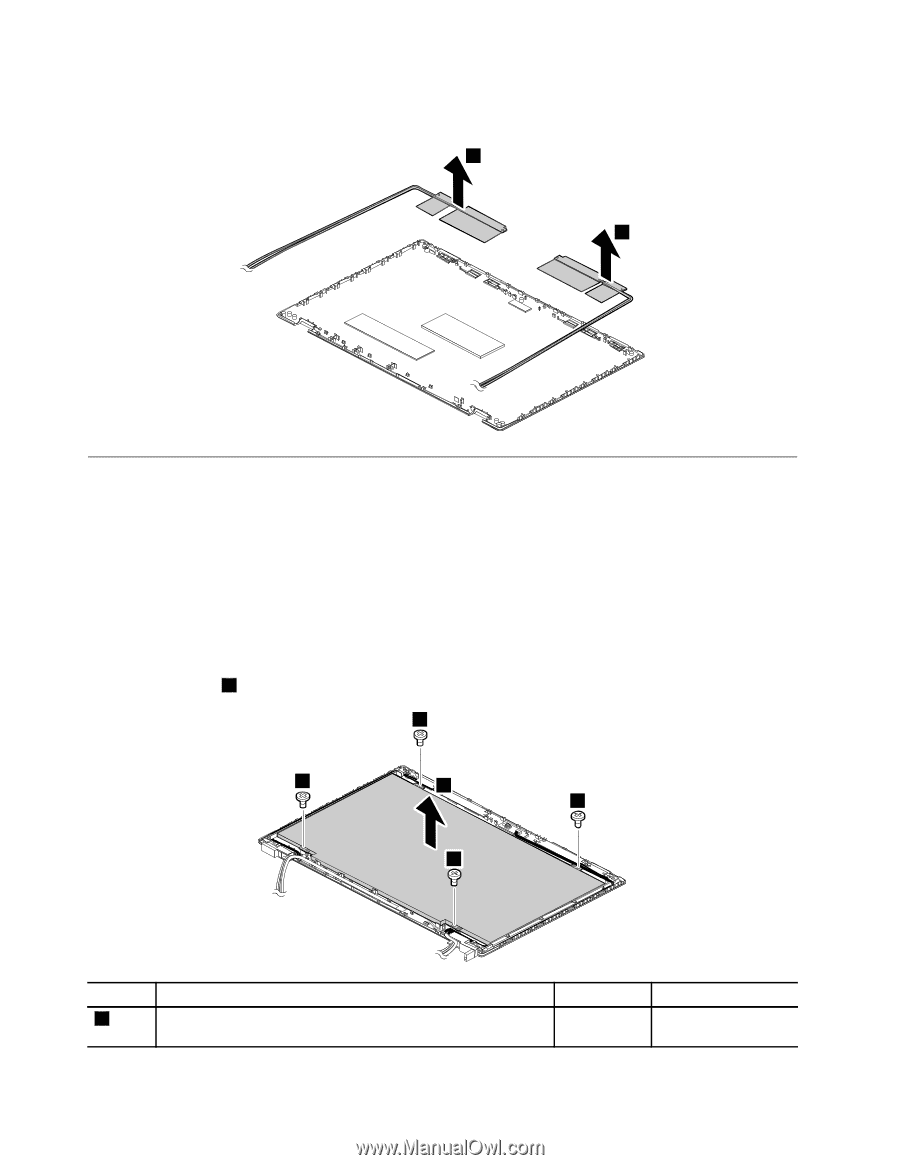
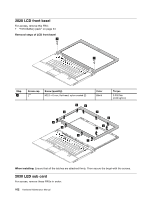
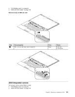
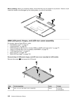
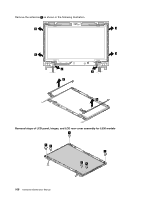
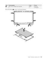
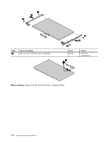
When installing: When you route the cables, ensure that they are not subject to any tension. Tension could cause the cables to be damaged by the cable guides, or a wire to be broken. 2 2 2060 LCD panel, hinges, and LCD rear cover assembly For access, remove these FRUs in order: • "1010 Battery pack" on page 64 • "1050 Keyboard" on page 69 • "1070 PCI Express Mini Card for wireless WAN or mSATA solid-state drive" on page 73 • "1080 PCI Express Mini Card for wireless LAN/WiMAX" on page 79 • "1100 Keyboard bezel" on page 82 • "2010 LCD unit" on page 100 • "2020 LCD front bezel" on page 102 Removal steps of LCD panel, hinges, and LCD rear cover assembly for L430 models Remove the screws 1 that secure the LCD panel. 1 1 2 1 1 Step 1 Screw (quantity) M2 × 3.5 mm, flat-head, nylon-coated (4) 106 Hardware Maintenance Manual Color Black Torque 0.181 Nm (1.85 kgfcm)
-
 1
1 -
2
-
3
-
4
-
5
-
6
-
7
-
8
-
9
-
10
-
11
-
12
-
13
-
14
-
15
-
16
-
17
-
18
-
19
-
20
-
21
-
22
-
23
-
24
-
25
-
26
-
27
-
28
-
29
-
30
-
31
-
32
-
33
-
34
-
35
-
36
-
37
-
38
-
39
-
40
-
41
-
42
-
43
-
44
-
45
-
46
-
47
-
48
-
49
-
50
-
51
-
52
-
53
-
54
-
55
-
56
-
57
-
58
-
59
-
60
-
61
-
62
-
63
-
64
-
65
-
66
-
67
-
68
-
69
-
70
-
71
-
72
-
73
-
74
-
75
-
76
-
77
-
78
-
79
-
80
-
81
-
82
-
83
-
84
-
85
-
86
-
87
-
88
-
89
-
90
-
91
-
92
-
93
-
94
-
95
-
96
-
97
-
98
-
99
-
100
-
101
-
102
-
103
-
104
-
105
-
106
-
 107
107 -
 108
108 -
 109
109 -
 110
110 -
 111
111 -
 112
112 -
 113
113 -
 114
114 -
 115
115 -
 116
116 -
 117
117 -
118
-
119
-
120
 |
 |