Lenovo ThinkPad L530 Hardware Maintenance Manual - Page 97
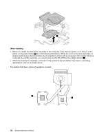
Thermal fan assembly, assembly or might cause the computer to malfunction.
 |
View all Lenovo ThinkPad L530 manuals
Add to My Manuals
Save this manual to your list of manuals |
Page 97 highlights
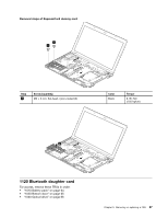
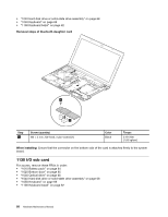
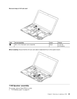
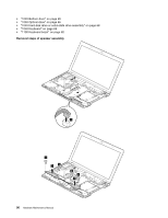
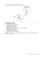
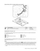
Step 2 Screw (quantity) M2 × 3 mm, flat-head, nylon-coated (4) Color Black Torque 0.392 Nm (4.00 kgfcm) 1150 Thermal fan assembly For access, remove these FRUs in order: • "1010 Battery pack" on page 64 • "1020 Bottom door" on page 65 • "1030 Optical drive" on page 66 • "1040 Hard disk drive or solid-state drive assembly" on page 68 • "1050 Keyboard" on page 69 • "1100 Keyboard bezel" on page 82 Attention: • Do not handle the thermal fan assembly roughly. Improper handling of the thermal fan assembly can cause distortion or deformation and imperfect contact with components. • Do not touch or apply any excessive force to the fan motor. It might cause damage to the thermal fan assembly or might cause the computer to malfunction. Removal steps of thermal fan assembly Detach the thermal fan assembly connector 1 . Loosen the screws 2 in ascending alphabetical order as illustrated, but do not remove them. 1 2f 2b 2d 2e 2c 2a Note: Some models might not have screws 2e and 2f . Chapter 9. Removing or replacing a FRU 91
-
 1
1 -
2
-
3
-
4
-
5
-
6
-
7
-
8
-
9
-
10
-
11
-
12
-
13
-
14
-
15
-
16
-
17
-
18
-
19
-
20
-
21
-
22
-
23
-
24
-
25
-
26
-
27
-
28
-
29
-
30
-
31
-
32
-
33
-
34
-
35
-
36
-
37
-
38
-
39
-
40
-
41
-
42
-
43
-
44
-
45
-
46
-
47
-
48
-
49
-
50
-
51
-
52
-
53
-
54
-
55
-
56
-
57
-
58
-
59
-
60
-
61
-
62
-
63
-
64
-
65
-
66
-
67
-
68
-
69
-
70
-
71
-
72
-
73
-
74
-
75
-
76
-
77
-
78
-
79
-
80
-
81
-
82
-
83
-
84
-
85
-
86
-
87
-
88
-
89
-
90
-
91
-
 92
92 -
 93
93 -
 94
94 -
 95
95 -
 96
96 -
 97
97 -
 98
98 -
 99
99 -
 100
100 -
 101
101 -
 102
102 -
103
-
104
-
105
-
106
-
107
-
108
-
109
-
110
-
111
-
112
-
113
-
114
-
115
-
116
-
117
-
118
-
119
-
120
 |
 |