Lexmark E310 Service Manual
Lexmark E310 - Optra B/W Laser Printer Manual
 |
UPC - 734646183000
View all Lexmark E310 manuals
Add to My Manuals
Save this manual to your list of manuals |
Lexmark E310 manual content summary:
- Lexmark E310 | Service Manual - Page 1
OptraTM E310/E312 4044-XXX • Table of Contents • Start Diagnostics • Safety and Notices • Trademarks • Index Lexmark and Lexmark with diamond design are trademarks of Lexmark International, Inc., registered in the United States and/or other countries. - Lexmark E310 | Service Manual - Page 2
errors. supply in any way it believes appropriate without incurring any obligation to you. You can purchase additional copies of publications related to this product by calling 1-800-553-9727. In other countries, contact your point of purchase. Lexmark and Optra are trademarks of Lexmark - Lexmark E310 | Service Manual - Page 3
and Safety Information v Laser Notice v Safety Information xv General Information 1-1 Options 1-1 Diagnostic Information 2-1 Start 2-1 Service Error Codes 2-2 User Error Message Table 2-6 Power-On Self Test (POST 2-9 Symptom Tables 2-10 Service Checks 2-12 Cooling Fan Service Check 2-12 - Lexmark E310 | Service Manual - Page 4
5-9 LVPS (model E312 5-14 High Voltage Power Supply (model E310 5-16 High Voltage Power Supply (model E312 5-18 Interconnect Board (model E310 5-21 Parts Catalog 6-1 Assembly 1: Covers 6-2 Assembly 2: Frame 6-6 Assembly 3: Fuser 6-10 Assembly 4: Main Drive 6-14 Assembly 5: Paper Feed 6-16 - Lexmark E310 | Service Manual - Page 5
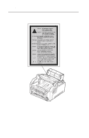
nominally a 5 milliwatt gallium arsenide laser operating in the wavelength region of 770-795 nanometers. The laser system and printer are designed so there is never any human access to laser radiation above a Class I level during normal operation, user maintenance, or prescribed service condition. v - Lexmark E310 | Service Manual - Page 6
4044-XXX Laser Advisory Label vi - Lexmark E310 | Service Manual - Page 7
4044-XXX Class 1 Laser Statement Label vii - Lexmark E310 | Service Manual - Page 8
4044-XXX Laser Der Drucker erfüllt gemäß amtlicher Bestätigung der USA die Anforderungen der Bestimmung DHHS (Department of Health and Human Services) 21 CFR Teil J für Laserprodukte der Klasse I (1). In anderen Ländern gilt der Drucker als Laserprodukt der Klasse I, der die Anforderungen der IEC ( - Lexmark E310 | Service Manual - Page 9
classe IIIb (3b) all'arseniuro di gallio della potenza di 5mW che opera sulla lunghezza d'onda compresa tra 770 e 795 nanometri. Il sistema laser e la stampante sono stati progettati in modo tale che le persone a contatto con la stampante, durante il normale funzionamento, le operazioni di servizio - Lexmark E310 | Service Manual - Page 10
CFR Subchapter J, voor andere landen in IEC 825. Laserprodukten van klasse I worden niet als ongevaarlijk aangemerkt. De printer is voorzien van een laser van klasse IIIb (3b), dat wil zeggen een gallium arsenide-laser van 5 milliwatt met een golflengte van 770-795 nanometer. Het lasergedeelte en de - Lexmark E310 | Service Manual - Page 11
med kravene i IEC 825. Klasse I-laserprodukter betragtes ikke som farlige. Printeren indeholder internt en Klasse IIIB (3b)-laser, der nominelt er en 5 milliwatt galliumarsenid laser, som arbejder på bølgelængdeområdet 770-795 nanometer. Lasersystemet og printeren er udformet således, at mennesker - Lexmark E310 | Service Manual - Page 12
utsätts för laserstrålning över Klass I-nivå vid normal användning, underhåll som utförs av användaren eller annan föreskriven serviceåtgärd. Laser-melding Skriveren er godkjent i USA etter kravene i DHHS 21 CFR, underkapittel J, for klasse I (1) laserprodukter, og er i andre land godkjent som et - Lexmark E310 | Service Manual - Page 13
4044-XXX Avís sobre el Làser Segons ha estat certificat als Estats Units, aquesta impressora compleix els requisits de DHHS 21 CFR, apartat J, pels productes làser de classe I (1), i segons ha estat certificat en altres llocs, és un producte làser de classe I que compleix els requisits d'IEC 825. - Lexmark E310 | Service Manual - Page 14
4044-XXX Japanese Laser Notice Chinese Laser Notice xiv - Lexmark E310 | Service Manual - Page 15
standards with the use of specific Lexmark components. The safety features of some parts may not always be obvious. Lexmark is not responsible for the use of other replacement parts. • The maintenance information for this product has been prepared for use by a professional service person and is not - Lexmark E310 | Service Manual - Page 16
et approuvé pour respecter les normes strictes de sécurité globale lors de l'utilisation de composants Lexmark spécifiques. Les caractéristiques de sécurité de certains éléments ne sont pas toujours évidentes. Lexmark ne peut être tenu responsable de l'utilisation d'autres pièces de rechange. • Les - Lexmark E310 | Service Manual - Page 17
Funktionen der Bauteile und Optionen sind nicht immer offensichtlich. Sofern Teile eingesetzt werden, die nicht von Lexmark sind, wird von Lexmark keinerlei Verantwortung oder Haftung für dieses Produkt übernommen. • Die Wartungsinformationen für dieses Produkt sind ausschließlich für die Verwendung - Lexmark E310 | Service Manual - Page 18
aprovado para satisfazer os padrões globais de segurança na utilização de componentes específicos da Lexmark. As funções de segurança de alguns dos componentes podem não ser sempre óbvias. A Lexmark não é responsável pela utilização de outros componentes de substituição. • As informações de seguran - Lexmark E310 | Service Manual - Page 19
4044-XXX Chinese Safety Information Korean Safety Information xix - Lexmark E310 | Service Manual - Page 20
4044-XXX xx - Lexmark E310 | Service Manual - Page 21
4044-XXX 1. General Information This printer is a letter-quality laser page printer designed to attach to an IBM Connectivity Resolution Starter Toner Cartridge Optra E310 4044-001 8 pages per minute 2MB Optra E312 4044-201 10 pages per minute 4MB Optra E312L 4044-2L1 10 pages per minute - Lexmark E310 | Service Manual - Page 22
Liquid Crystal Display Light-Emitting Diode Low Voltage Power Supply Masked Read Only Memory Nonvolatile Random Access Memory Original Equipment Manufacturer Photoconductor Power-On Self Test Read Only Memory Single In-Line Memory Module Static Random Access Memory Used Parts Return Universal Serial - Lexmark E310 | Service Manual - Page 23
a malfunctioning printer. The lights on the operator panel can indicate either a user error message or service error message. When a service error occurs, the printer stops printing and all operator panel LEDs blink in a continuous pattern, indicating a service error, until the printer is powered - Lexmark E310 | Service Manual - Page 24
button to view the secondary service error code. Go to "Secondary Service Error Codes" on page 2-5. Laser Diode Failure Inspect the printhead cable and replace as necessary. Replace the printhead assembly. If this does not correct the problem, replace the engine/LVPS board. 2-2 Service Manual - Lexmark E310 | Service Manual - Page 25
4044-XXX Blinking Operator Panel LED Mirror Motor Failure Action Inspect the printhead cable and replace as necessary. Replace the printhead assembly. If this does not correct the problem, replace the engine/LVPS board. Optional Memory Error Replace the optional memory SIMM. If this does not - Lexmark E310 | Service Manual - Page 26
SIMM w/Flash. If this does not correct the problem, replace the controller board. Font Checksum Failure Error Replace the ROM SIMM. If this does not correct the problem, replace the controller board. Engine/LVPS Board Communications Failure Error Replace the engine/LVPS board 2-4 Service Manual - Lexmark E310 | Service Manual - Page 27
second service error code is used to further describe the error. When a service error occurs, pressing the operator panel button after viewing the primary service error code displays the secondary service error code. The following table contains the secondary service error codes. Blinking Operator - Lexmark E310 | Service Manual - Page 28
on solid or blinking until the printer is powered off. Locate the printer's LED Status in the following table and take the indicated action. User Error Message Paper Jam Load Manual Paper/ Envelope Load Paper/Load Envelope Top Cover Open LED Status Paper Jam on solid Load Paper blinks and Press - Lexmark E310 | Service Manual - Page 29
4044-XXX User Error Message Memory Full/Complex Page/Resolution Reduction Warning/ Font Error/ Resource Save Off Deficient Memory Flash Memory Full LED Status Error on solid and Press Button on solid Error blinks and Press Button on solid Action The printer memory is full or the page is too - Lexmark E310 | Service Manual - Page 30
Press Button on solid Ready, Data blinking and the Error, Press Button on solid Action Switch the printing mode to a different printing mode using the Lexmark driver for Windows, or push the operator panel button to resume printing, or do an operator panel reset by pressing and holding the operator - Lexmark E310 | Service Manual - Page 31
Data blinking and Error, Press Button on solid Ready blinking and Error, Press Button on solid Action The print command is requesting a font that is not present or installed. The user must select a different font or try turning the Best Fit setting on and retry the print command. The printer lacks - Lexmark E310 | Service Manual - Page 32
2-17. Go to the "Hot Fuser Service Check" on page 2-21. Go to the "Paper Feed Service Check" on page 2-24. Base Printer Symptom Table Symptom Dead Machine (no power) Fan noisy or not working Fuser parts melted Fuser lamp doesn't light Toner not fused to the paper Action Go to the "Dead Machine - Lexmark E310 | Service Manual - Page 33
Blank page Black page Heavy background Light print White or black lines or bands Toner on back of page Incorrect characters print Paper jams Main Motor noisy or does not move Paper never picks Paper feeds continuously Paper skew Printer not communicating with host Paper wrinkled or bent Top cover - Lexmark E310 | Service Manual - Page 34
printer positioned on its left side. This provides the servicer access to the various circuit boards underneath the printer while supplying necessary power to the rest of the printer. Cooling Fan Service replace the cooling fan. FRU Model E312 Engine Board Cooling Fan Action Make sure Service Manual - Lexmark E310 | Service Manual - Page 35
-XXX Cover Open Switch Service Check Note: Make sure a toner cartridge is installed and the cover closes all the way, engaging the cover open switch lever. The lever can easily be positioned incorrectly if the top cover has been removed and replaced. FRU Models E310 & E312 Cover Open Switch Model - Lexmark E310 | Service Manual - Page 36
should be within the following limits: 100 V ac - 127 V ac for the low voltage model printer 200 V ac - 240 V ac for the high voltage model printer FRU Model E310 & E312 LVPS Fuse 2-14 Service Manual Action Check the fuse on the LVPS for continuity. Replace with the appropriate fuse if blown. If - Lexmark E310 | Service Manual - Page 37
Switch Model E310 LVPS to Interconnect Board Cable Model E310 Interconnect Board Model E312 Power Switch Action Disconnect the cables from CN2 and CN5 and leave the cables connected to the power switch attached. With the printer positioned on its left side and the engine/LVPS board positioned on - Lexmark E310 | Service Manual - Page 38
the engine board. Disconnect all other cables from the engine board. Go to the "Engine Board (model E312)" on page -9. Check the voltage measurements at each connector. If any voltages are incorrect, replace the connecting one of the cables, replace the FRU that you connected. 2-16 Service Manual - Lexmark E310 | Service Manual - Page 39
4044-XXX Fuser Service Check Cold Fuser Service Check When toner is partially fused to the paper, it is usually caused to the printer must be within the following limits: 100 V ac - 127 V ac for the low voltage model printer 200 V ac - 240 V ac for the high voltage model printer Turn the printer off - Lexmark E310 | Service Manual - Page 40
4044-XXX The fuser lamp does light FRU Model 310 Thermistor Model 312 Thermistor Models E310 & E312 Fuser Lamp Action If the fuser lamp comes on and a fuser failure LED error code displays, be sure the thermistor is contacting the hot roll and the thermistor cable is firmly seated in connector CN1 - Lexmark E310 | Service Manual - Page 41
The fuser lamp does not light FRU Model E310 Fuser Lamp Lamp Cable Thermistor LVPS Action Turn the printer off and disconnect the fuser lamp the fuser thermistor is correctly connected to CN1 on the LVPS. If the problem persists, disconnect the thermistor cable from CN1 on the LVPS board and - Lexmark E310 | Service Manual - Page 42
4044-XXX FRU Model E312 Fuser Lamp Lamp Cable Thermistor LVPS Action Turn the printer off and disconnect the is correctly connected to CN10 on the engine board. If the problem persists, disconnect the thermistor cable from CN1o on the engine board and correct, replace the lamp. 2-20 Service Manual - Lexmark E310 | Service Manual - Page 43
-XXX Hot Fuser Service Check FRU Model E310 Fuser Thermistor Model E312 Fuser Thermistor Models E310 & E312 Fuser Lamp Action the correct voltage fuser lamp is installed. Replace if necessary. Main Motor Service Check FRU Model E310 Interconnect Board Main Motor Main Motor Cable Action Check - Lexmark E310 | Service Manual - Page 44
4044-XXX FRU Model E312 Engine Board Main Motor Main Motor Cable Action Check the engine board for the following voltages: CN2-3 +24 V dc CN2-4 +24 V dc If exists on each wire, replace the main motor. If continuity does not exist on one or more of the wires, replace the cable. 2-22 Service Manual - Lexmark E310 | Service Manual - Page 45
Service Check Inspect the operator panel cable for damage. Make sure the cable is plugged in securely. Run POST and check each LED for proper operation. FRU Models E310 & E312 Operator Panel Operator Panel Cable Models E310 & E312 the following voltages with the printer on at idle: U5-1: Ground - Lexmark E310 | Service Manual - Page 46
panel cable. Paper Feed Service Check Paper Jam error indication during POST FRU Models E310 & E312 Exit Sensor Flag Models E310 & E312 Input Paper Feed Sensor Action If the exit sensor flag is not resting within the paper exit sensor during POST, the printer displays a paper jam message. Make - Lexmark E310 | Service Manual - Page 47
picks but stops about an inch down the page FRU Models E310 & E312 Roller Guides Action Check for correct position of roller guides on pick roller assembly. Paper picks but stops half way through the printer FRU Model E310 Input Paper Feed Sensor Interconnect Board Action Make sure the input - Lexmark E310 | Service Manual - Page 48
4044-XXX FRU Model E312 Input Paper Feed Sensor Engine Board Action Make sure the input paper feed sensor is working properly. Check for a broken or stuck flag on the input paper feed sensor. Check , replace the engine board. If correct, replace the input paper feed sensor. 2-26 Service Manual - Lexmark E310 | Service Manual - Page 49
Models E310 & E312 Paper Tray Model E310 Pick Roller Solenoid Model E312 Pick Roller Solenoid Action Make sure the paper tray is correctly installed. The black mylar guide sheet in the front of the tray must be positioned in the paper path just behind the pick roller assembly. This guide sheet can - Lexmark E310 | Service Manual - Page 50
transfer roller. A worn transfer roller causes the printer to run hotter than required for the media being printed. Excessive heat can cause paper treeing problems, poor stacking or curl. Print Quality Service Check Blank page FRU Action Models E310 & E312 Toner Cartridge Printhead Printhead - Lexmark E310 | Service Manual - Page 51
4044-XXX Black page Note: Incorrect laser exposure or incorrect charging of the photoconductor causes an all black page. FRU Models E310 & E312 HVPS Contacts Model E310 Engine/LVPS Board HVPS Cable HVPS Model E312 Engine Board HVPS Cable HVPS Action Check the contacts for contamination and correct - Lexmark E310 | Service Manual - Page 52
/LVPS Board Check the contacts for correct installation and contamination where contact is made with the toner cartridge and HVPS Board. Clean as necessary. If this does not correct the problem, replace the following FRUs one at a time in the order shown: HVPS Board Engine Board 2-30 Service Manual - Lexmark E310 | Service Manual - Page 53
(no periodic pattern) FRU Toner Cartridge Fuser Backup Roller Springs Paper Action Remove the toner cartridge and gently shake the assembly to evenly distribute the toner. If toner cartridge is low, try a new one. Check left and right backup roller springs and backup roller to ensure adequate even - Lexmark E310 | Service Manual - Page 54
or damaged. Inform the customer to replace the toner cartridge. The supply roller or gear driving the supply roller may be contaminated or damaged. Inform the customer to replace the toner cartridge. The supply roller or gear driving the developer roller may be contaminated or damaged. Inform the - Lexmark E310 | Service Manual - Page 55
fuse the toner to the paper. Go to the "Cold Fuser Service Check" on page 2-17. Make sure recommended paper is being used. Action Make sure the toner cartridge is installed correctly and is not low on toner. If the problem continues, install a new toner cartridge. Check the transfer roller for signs - Lexmark E310 | Service Manual - Page 56
the paper as it feeds through the printer especially in the developer and transfer process. Inspect the toner cartridge and paper feed components, especially the drive gears, for signs of wear, debris, binds or damage. Toner on back of page FRU Print Cartridge Fuser Hot Roll Backup Roller Transfer - Lexmark E310 | Service Manual - Page 57
Service Check 1. Perform a print test to make sure the printer prints correctly. 2. Be sure the printer cable is designed for bidirectional printing. 3. Be sure the user the user application/printer driver is set up correctly and the correct bidirectional parallel cable is installed, yet the printer - Lexmark E310 | Service Manual - Page 58
4044-XXX 2-36 Service Manual - Lexmark E310 | Service Manual - Page 59
identify printer failures and verify that repairs have corrected the problem. Memory printer. Release the button once the Error LED comes on solid. 4. Close the top cover. 5. If all the diagnostic tests run correctly, the Data LED blinks. If a test fails, the Error LED pattern for the service error - Lexmark E310 | Service Manual - Page 60
button press until all LEDs come on solid. 9. The test pages are printing. 10. When the test pages have finished printing, the Ready LED comes on solid and the Data LED goes off. Note: After the print quality test pages print, the printer automatically returns to the Ready mode. 3-2 Service Manual - Lexmark E310 | Service Manual - Page 61
panel button. 3. The Ready LED comes on solid and the Data LED blinks indi- cating the printer is busy. 4. The test page prints and the operator panel Ready LED comes on solid and the Data LED turns off. 5. The printer returns to the Ready mode. Configuration Mode The configuration mode gives the - Lexmark E310 | Service Manual - Page 62
Double-click the operator panel button two times. The Load Paper LED comes on solid while the Error and Press Button LEDs continue blinking. 7. Perform a long button press. All LEDs blink once. The Ready LED stays on solid. The printer is in the configuration mode. 8. To exit the configuration mode - Lexmark E310 | Service Manual - Page 63
the configuration menu. The first time through the menu the LED selected is on solid. The second time through the menu the LED selected is blinking. First pass - LED on solid overlay. Parallel Port Parallel NPA Parallel Protocol PPDS CRLF/LFCR Off/On/Auto Operator Panel Button Second pass - LED - Lexmark E310 | Service Manual - Page 64
Port Parallel Port allows the user to enable or disable the . When the LED is *blinking, the parallel port is enabled. 2. Perform blink once, indicating the setting is saved. 4. Exit the configuration mode by turning the printer host and the printer. Perform the the printer must be in NPA packets. Any non- - Lexmark E310 | Service Manual - Page 65
press. All LEDs blink once, indicating the setting is saved. 6. Exit the configuration mode by turning the printer power off. Parallel Protocol The printer supports two parallel protocol settings to the PPDS item on the configuration menu. The PPDS (Paper Jam) LED comes on solid. Diagnostic Aids 3-7 - Lexmark E310 | Service Manual - Page 66
moves to the CRLF/LFCR item on the configuration menu. The CRLF/ LFCR (Error) LED comes on solid. 3. The current CRLF/LFCR setting is indicated by the press. All LEDs blink once, indicating the setting is saved. 6. Exit the configuration mode by turning the printer power off. Parallel Service Manual - Lexmark E310 | Service Manual - Page 67
to select the Parallel Mode 2 setting. 4. Perform a long button press. All LEDs blink once, indicating the setting is saved. 5. Exit the configuration mode by turning the printer power off. Parallel Strobe This setting allows the user to adjust the factory setting for the amount of time strobe is - Lexmark E310 | Service Manual - Page 68
Paper Jam) LED is blinking blinking, the USB Port is enabled. Perform a brief button press to select a different USB Port setting. 4. Perform a long button press. All LEDs blink once, indicating the setting is saved. 5. Exit the configuration mode by turning the printer power off. 3-10 Service Manual - Lexmark E310 | Service Manual - Page 69
to help isolate the cause of print problems. When a job is printed, the printer operator panel displays the Hex Trace indication, (Ready LED blinking), showing that the printer remains in the Hex Trace mode. Turn the printer power off or do an operator panel reset (long button press) to exit the Hex - Lexmark E310 | Service Manual - Page 70
comes on solid and the Error and Press Button LEDs continue blinking. 7. Double-click the operator button three times. The Paper Jam LED comes on solid while the Error and Press Button LEDs continue blinking. 8. Perform a long button press until all LEDs come on solid. The printer is in Hex Trace - Lexmark E310 | Service Manual - Page 71
mode. The cleaning mode helps eliminate small specs of toner present in the background when printing. Perform the following steps to perform the Engine Clean Cycle: 1. Turn the printer power off. 2. Open the top cover. 3. Turn the printer power on. 4. When the Error LED comes on solid, double-click - Lexmark E310 | Service Manual - Page 72
moves through the printer. Images are created with toner on an OPC drum within the toner cartridge. A transfer roller then draws the toner off the OPC drum onto the paper. Once the toner is affixed to the paper by the fuser, the paper exits either the top or front of the printer. 3-14 Service Manual - Lexmark E310 | Service Manual - Page 73
4044-XXX Paper Path Diagnostic Aids 3-15 - Lexmark E310 | Service Manual - Page 74
4044-XXX 3-16 Service Manual - Lexmark E310 | Service Manual - Page 75
CAUTION: Read the following before handling electronic parts. Handling ESD-Sensitive Parts Many electronic products use parts that are known to be sensitive to electrostatic discharge (ESD). To prevent damage to ESD-sensitive parts, follow the instructions below in addition to all the usual - Lexmark E310 | Service Manual - Page 76
one of the covers removed. Be sure to remove the print cartridge before you perform removal procedures. Screw Identification Table Type 1 Screw Type 2 Screw Type 3 Screw Type 4 Screw Covers Front Cover and Face Up Cover 1. Press the cover inward to release it and pull it forward. 4-2 Service Manual - Lexmark E310 | Service Manual - Page 77
4044-XXX 2. Remove the face up cover. 3. Open the front cover. Repair Information 4-3 - Lexmark E310 | Service Manual - Page 78
4044-XXX 4. Remove the screw from the support on each side of the printer. Note: If you want to remove the front cover only, remove the two screws and then remove the panel board and board cover. 4-4 Service Manual - Lexmark E310 | Service Manual - Page 79
4044-XXX Rear and Top Cover 1. Remove the three screws, press the retaining tabs and remove the rear cover. 2. Remove the front cover and face up cover. 3. Remove the two screws and remove the top cover. Repair Information 4-5 - Lexmark E310 | Service Manual - Page 80
4044-XXX Side Covers 1. Remove the front cover, face up cover, top cover and rear cover. 2. Remove the two screws securing the rear of each side cover. 3. Release the side cover tabs as shown and remove the left and right side covers. 4-6 Service Manual - Lexmark E310 | Service Manual - Page 81
4044-XXX Frame Assembly 1. Remove all covers. 2. Remove the HVPS. 3. Remove the two screws and remove the solenoid. 4. Remove the six screws and remove the frame assembly. Repair Information 4-7 - Lexmark E310 | Service Manual - Page 82
wire mounting screws (B). 4. Unplug the connector from the engine/LVPS board. 5. Remove the two fuser mounting screws (C). 6. Release the two snaps holding the fuser down. 4-8 Service Manual - Lexmark E310 | Service Manual - Page 83
4044-XXX 7. Slide the fuser in the direction of the arrows and remove the fuser. Note: The backup roller can fall from the printer if the printer is turned on its side with the fuser removed. Repair Information 4-9 - Lexmark E310 | Service Manual - Page 84
4044-XXX HVPS 1. Remove all covers. 2. Remove the HVPS board mounting screws. 4-10 Service Manual - Lexmark E310 | Service Manual - Page 85
HVPS. 4. Unplug the cable from the lower connector inside the HVPS and remove the HVPS. Note: The high voltage contacts can fall from the printer with the HVPS removed. Three contacts with the shorter springs are installed in the hole marked L+S. The contact with the longer spring is installed in - Lexmark E310 | Service Manual - Page 86
4044-XXX Interconnect Board (model E310) 1. Remove the LVPS. 2. Unplug all connectors from the interconnect board. 3. Remove the screws and remove the interconnect board. 4-12 Service Manual - Lexmark E310 | Service Manual - Page 87
4044-XXX Engine/LVPS Board (model E310) 1. Turn the printer upside down. 2. Remove all screws securing the SIMM access panel. 3. Remove the SIMM access panel. Repair Information 4-13 - Lexmark E310 | Service Manual - Page 88
4044-XXX 4. Unplug all the connectors from the engine/LVPS board. 5. Remove the five screws and remove the engine/LVPS board. 4-14 Service Manual - Lexmark E310 | Service Manual - Page 89
4044-XXX Engine/LVPS Board (model E312) 1. Turn the printer upside down. 2. Remove all screws securing the SIMM access panel. 3. Remove the SIMM access panel. Repair Information 4-15 - Lexmark E310 | Service Manual - Page 90
the printer and disconnect all the cables from the LVPS. 6. Remove the screws mounting the LVPS to the shield and remove the LVPS. 7. Disconnect all the cables from the engine board. 8. Remove the screws mounting the engine board to the lower frame and remove the engine board. 4-16 Service Manual - Lexmark E310 | Service Manual - Page 91
4044-XXX Main Drive Assembly 1. Remove all covers. 2. Remove the six main drive assembly mounting screws. 3. Unplug the connector and remove the main drive assembly. Repair Information 4-17 - Lexmark E310 | Service Manual - Page 92
4044-XXX Pick Roll Assembly 1. Remove all the covers. 2. Remove the high voltage power supply. 3. Remove the roller bearing. 4-18 Service Manual - Lexmark E310 | Service Manual - Page 93
4044-XXX 4. Remove the roller access cover on the left side of the pick roller assembly. 5. Remove the upper frame. 6. Remove the pick up roller gear and clutch. 7. Lift the pick roll assembly from the printer. Repair Information 4-19 - Lexmark E310 | Service Manual - Page 94
4044-XXX Printhead Assembly 1. Remove the top cover. 2. Unplug all the connectors from the printhead. 3. Remove the four mounting screws and remove the printhead. Note: Be sure to transfer the snap-on torroids when replacing the printhead cable. 4-20 Service Manual - Lexmark E310 | Service Manual - Page 95
4044-XXX Transfer Roll 1. Remove the front cover and face up cover. 2. Remove the black cover on the left end of the transfer roll. 3. Press the latches on the bearings to release them from the lower frame. 4. Lift the transfer roll from the printer. Repair Information 4-21 - Lexmark E310 | Service Manual - Page 96
4044-XXX 4-22 Service Manual - Lexmark E310 | Service Manual - Page 97
4044-XXX 5. Connector Locations Controller Board (model E310/E312) Connector J1 Printhead U5 Operator Panel (signals at idle) J7 Engine/LVPS Board dc 5 +5 V dc 6 +5 V dc 7 Ground 8 +5 V dc 9 +5 V dc 10 +5 V dc 11 Ground 12 +5 V dc 13 +5 V dc 14 +5 V dc Connector Locations 5-1 - Lexmark E310 | Service Manual - Page 98
4044-XXX Connector J7 (continued) Pin No. Signal 15 +5 V dc 16 +5 V dc 17 +5 V dc 18 Ground 19 Ground 20 Ground 21 Ground 22 Ground 23 +5 V dc 24 +5 V dc 5-2 Service Manual - Lexmark E310 | Service Manual - Page 99
4044-XXX Connector Locations 5-3 - Lexmark E310 | Service Manual - Page 100
/Printhead Pin No. Signal 1 AC In 2 AC In 1 AC In 2 AC In 1 THERM 2 +3.9 V dc 1 +24 V dc SWITCH 2 +24 V dc 3 Ground 4 +24 V dc 5 VDO 6 MHV 7 LDON 8 SUPPLY 9 Ground 10 DEV350 5-4 Service Manual - Lexmark E310 | Service Manual - Page 101
4044-XXX Connector CN2 (continued) Pin No. Signal 11 HSYNC 12 THVPWM 13 EXT CLK 14 Ground 15 Ground 16 THVEA 17 LREADY 18 DEV300 19 P MOTOR 20 +5 V dc 21 AGND 22 AGND 23 THVREAD 24 AGND Connector Locations 5-5 - Lexmark E310 | Service Manual - Page 102
CN4 Interconnect Board Pin No. Signal 1 DEV FUSE FAN J 2 MOTOR EA J 3 MOTOR PB J 4 MOTOR PA J 5 AGND 6 NEW DEV J 7 PFEED J 8 AGND 9 Ground 10 Ground 11 CLUTCH J 12 PEMPTY J 13 +24 V dc 14 PNARROW J 15 +5 V dc 16 +24 V dc 17 PTL J 18 +5 V dc 19 PMOTOR EXT J 20 - Lexmark E310 | Service Manual - Page 103
4044-XXX Connector CN5 Controller Board Pin No. Signal 1 EBUSY 2 Not Used 3 EMSG 4 EXITPAP 5 CCLK 6 PRINT 7 VDI 8 Not Used 9 PSYNC 10 READY 11 HSYNC 12 Not Used 13 +5 V dc 14 CMSG 15 +5 V dc 16 +5 V dc 17 Ground 18 +5 V dc 19 Ground 20 Ground 21 Ground 22 - Lexmark E310 | Service Manual - Page 104
4044-XXX 5-8 Service Manual - Lexmark E310 | Service Manual - Page 105
4044-XXX Engine Board (model E312) Connector CN1 Controller Board Pin No. Signal 1 EBUSY 2 Not Used 3 EMSG 4 EXITPAP 5 CCLK 6 PRINT 7 VDI 8 Not Used 9 PSYNC 10 READY 11 HSYNC 12 Not Used 13 +5 V dc 14 CMSG 15 +5 V dc 16 +5 V dc 17 Ground, Floating 18 +5 V dc 19 - Lexmark E310 | Service Manual - Page 106
Feed/Paper Narrow Sensor Pin No. Signal 1 OUTA 2 OUTB 3 +24 V dc 4 +24 V dc 5 OUTA* 6 OUTB* 1 +24 V dc Switch 2 Not Used 3 Fan 1 +24 V dc Switch 2 Clutch 1 PEMPTY 2 +5 V dc 3 Ground, Floating 1 P Feed 2 P Width 3 +5 V dc 4 Ground, Floating 5-10 Service Manual - Lexmark E310 | Service Manual - Page 107
Pin No. Signal 1 +5 V dc 2 +5 V dc 3 Ground, Floating 4 Ground, Floating 5 Fuser On 6 +24 V dc Switch 7 Ground 8 Ground 9 +24 V dc 10 +24 V dc 1 PTL 2 Ground, Floating 1 Not Used 2 Not Used 3 Not Used 4 Not Used 1 THERM 2 Not Used 3 Ground, Floating Connector - Lexmark E310 | Service Manual - Page 108
Pin No. Signal 1 +24 V dc 2 +24 V dc Switch 3 +24 V dc 4 +24 V dc Switch 5 LREADY 6 THVEA 7 VDO 8 THV PWM 9 HSYNC 10 MHV PWM 11 DEVEA-A 12 Supply EA 13 LDON 14 DEVEA-B 15 Ground, Floating 16 Ground, Floating 17 Ground, Floating 18 +5 V dc 19 Ground 20 +5 V dc - Lexmark E310 | Service Manual - Page 109
4044-XXX Connector Locations 5-13 - Lexmark E310 | Service Manual - Page 110
E312) Connector CN501 Power Switch CN502 Fuser Lamp CN503 Engine Board Pin No. Signal 1 AC In 2 AC In 1 AC In 2 AC In 1 +5 V dc 2 +5 V dc 3 Ground, Floating 4 Ground, Floating 5 Fuser On 6 +24 V dc Switch 7 Ground 8 Ground 9 +24 V dc 10 +24 V dc 5-14 Service Manual - Lexmark E310 | Service Manual - Page 111
4044-XXX Connector Locations 5-15 - Lexmark E310 | Service Manual - Page 112
(model E310) Connector CN1 Engine/LVPS Board Pin No. Signal 1 +24 V dc 2 +24 V dc SWITCH 3 +24 V dc 4 Ground 5 MHV 6 VDO 7 SUPPLY 8 LDON 9 DEV350 10 Ground 11 THVPWM 12 HSYNC 13 Ground 14 EXT CLK 15 THVEA 16 Ground 17 DEV300 18 LREADY 19 +5 V dc 20 P MOTOR - Lexmark E310 | Service Manual - Page 113
4044-XXX Connector CN2 Cover Open Switch CN3 Printhead CN4 Printhead Pin No. Signal 1 +24 V dc SWITCH 2 Not Used 3 +24 V dc 1 +24 V dc SWITCH 2 AGND 3 P MOTOR 4 LREADY 5 EXT CLK 1 HSYNC 2 +5 V dc SWITCH 3 Ground 4 LDON 5 VDO 6 Ground Connector Locations 5-17 - Lexmark E310 | Service Manual - Page 114
4044-XXX High Voltage Power Supply (model E312) Connector CN1 Engine Board Pin No. Signal 1 +24 V dc SWITCH 2 +24 V dc 3 +24 V dc SWITCH 4 + 24 V dc 5 THVEA 6 LREADY 7 THV PWM 8 VDO 9 MHV PWM 10 HSYNC 11 SUPPLYEA 12 DEVEA-A 13 DEVEA-B 14 LDON 15 Ground, Floating 16 - Lexmark E310 | Service Manual - Page 115
4044-XXX Connector CN2 Cover Open Switch CN3 Printhead CN4 Printhead Pin No. Signal 1 +24 V dc SWITCH 2 +5 V dc SWITCH 3 +5 V dc 4 +24 V dc 1 +24 V dc SWITCH 2 AGND 3 P MOTOR 4 LREADY 5 EXT CLK 1 HSYNC 2 +5 V dc SWITCH 3 Ground, Floating 4 LDON 5 VDO 6 Not Used - Lexmark E310 | Service Manual - Page 116
4044-XXX 5-20 Service Manual - Lexmark E310 | Service Manual - Page 117
4044-XXX Interconnect Board (model E310) Connector Pin No. CN401 Paper Feed/Paper 1 Narrow Sensor 2 3 4 CN402 Clutch 1 2 CN403 Paper Empty 1 Sensor 2 3 CN404 Developer Fuse 1 2 CN405 Main Motor 1 2 3 4 5 6 Signal PFEED J PNARROW J +5 V dc Ground +24 V dc CLUTCH J PEMPTY J +5 - Lexmark E310 | Service Manual - Page 118
4044-XXX Connector CN406 Engine/LVPS Board CN407 Pre-Transfer LED (PTL) CN408 Cooling Fan Pin No. 1 2 3 4 5 6 7 8 9 10 11 12 13 14 15 16 17 18 19 20 1 2 1 2 3 Signal MOTOR EA J DEV FUSE FAN J MOTOR PA J MOTOR PB J NEW DEV J AGND AGND PFEED J - Lexmark E310 | Service Manual - Page 119
4044-XXX Connector Locations 5-23 - Lexmark E310 | Service Manual - Page 120
4044-XXX 5-24 Service Manual - Lexmark E310 | Service Manual - Page 121
machines. • NS: (Not Shown) in the Asm-Index column indicates that the part is procurable but is not pictured in the illustration. • PP: (Parts Packet) in the parts description column indicates the part is contained in a parts packet. • INDENTURE: The indenture is marked by a series of dots located - Lexmark E310 | Service Manual - Page 122
4044-XXX Assembly 1: Covers 6-2 Service Manual - Lexmark E310 | Service Manual - Page 123
12G1846 12G1874 12G3668 12G0112 Units 1 1 1 1 1 1 2 1 1 1 1 1 6 2 1 1 1 1 1 Description Extender, Paper Support Support, Paper E310 Support, Paper E312 Cover Asm, Cooling Air/Stacker Stacker Assembly, Paper Support, Open Cover Guide, Paper Stacker Button, Operator Panel Lens, Operator Panel Panel - Lexmark E310 | Service Manual - Page 124
4044-XXX Assembly 1: Covers (continued) 6-4 Service Manual - Lexmark E310 | Service Manual - Page 125
4044-XXX AsmIndex 1-17 1-17 1-18 1-19 1-20 1-21 1-22 1-23 1-24 Part Number 12G0035 12G1938 12G0098 12G1847 12G0037 12G0040 12G0041 12G0176 Units 1 1 1 7 1 1 1 1 1 Description Tray Asm, Paper E310 Tray Asm, Paper E312 Cover Asm, Rear Screw, Type 1 PP 12G0101 Cover, Right Side Cover, Lower Front - Lexmark E310 | Service Manual - Page 126
4044-XXX Assembly 2: Frame 6-6 Service Manual - Lexmark E310 | Service Manual - Page 127
2-5 2-5 2-6 2-6 2-7 2-8 2-9 2-10 2-11 2-11 2-12 2-12 2-13 2-14 2-14 Part Number 12G0099 12G0046 12G1879 12G0125 12G1882 12G0047 E312 Solenoid, Pick Roller Clutch E310 Solenoid, Pick Roller Clutch E312 Fan, Cooling Spring, Print Cartridge Lock Lock, Print CartrIdge, Right Lock, Print Cartridge - Lexmark E310 | Service Manual - Page 128
4044-XXX Assembly 2: Frame (continued) 6-8 Service Manual - Lexmark E310 | Service Manual - Page 129
30 2-30 2-31 2-31 2-32 2-33 2-34 Part Number 12G0048 12G0057 12G1887 12G0049 12G0119 12G1931 12G0127 12G0120 Paper Feed/Size E310 Sensor Asm, Input Paper Feed/Size E312 Cable Asm, Fuser Lamp Flag, Paper Exit Sensor E310 Flag, Paper Exit Sensor E312 Guide, HV Contact Contact Asm, HV-Transfer Roller - Lexmark E310 | Service Manual - Page 130
4044-XXX Assembly 3: Fuser 6-10 Service Manual - Lexmark E310 | Service Manual - Page 131
Bearing, Fuser Exit Roller Gear, Fuser Exit Roller Roller Asm, Fuser Exit/Redrive Gear, Redrive, Idler #2 Gear, Redrive, Idler #1 Spring, Redrive Roller Roller Asm, Redrive Finger, Detack E310 Finger, Detack E312 Spring, Detack Finger Spring, Fuser Exit Roller Roller, Fuser Exit Parts Catalog 6-11 - Lexmark E310 | Service Manual - Page 132
4044-XXX Assembly 3: Fuser (continued) 6-12 Service Manual - Lexmark E310 | Service Manual - Page 133
V ac E310 Lamp, Fuser, 220 V ac E312 Plate, Hot Roll Ground Gear, Fuser Hot Roll Bearing, Right Hot Roll Bearing Asm, Backup Roll Roller Asm, Exit Paper Feed Bushing, Exit Paper Feed Roller Roller, Backup Hot Roll, Fuser Bearing, Left Hot Roll Frame, Fuser E310 Frame, Fuser E312 Parts Catalog 6-13 - Lexmark E310 | Service Manual - Page 134
4044-XXX Assembly 4: Main Drive 6-14 Service Manual - Lexmark E310 | Service Manual - Page 135
4-6 4-7 4-8 4-9 4-10 4-11 Part Number 12G0042 12G1877 12G0044 Units 1 1 1 5 1 1 1 6 1 1 1 1 Description Main Drive Assembly E310 Main Drive Assembly E312 Motor Asm, Main Screw, Type 4 PP 12G0101 Gear, Drive Feed 1 PP 12G0102 Gear, Drive Feed 2 PP 12G0102 Gear, Input Paper Feed PP 12G0102 Screw - Lexmark E310 | Service Manual - Page 136
4044-XXX Assembly 5: Paper Feed 6-16 Service Manual - Lexmark E310 | Service Manual - Page 137
1 1 1 2 1 1 1 1 1 1 Description Holder Asm, Spring Spring, Pad Asm, Rear Pad Asm, Pick Roller Spring, Pad Asm, Lower Spring, Separator Asm Clip, E PP 12G0101 Clutch Asm, Pick Roller Roller Asm, Pick E310 Roller Asm, Pick E312 Bearing, Left Pick Roller Shaft Separator Asm, Paper Parts Catalog 6-17 - Lexmark E310 | Service Manual - Page 138
4044-XXX Assembly 5: Paper Feed (continued) 6-18 Service Manual - Lexmark E310 | Service Manual - Page 139
12G0070 12G1889 12G0073 12G0071 Units 1 1 2 1 1 1 1 Description Shaft Asm, Input Paper Feed E310 Shaft Asm, Input Paper Feed E312 Separator, Secondary Paper E310 Roller Asm, Input Paper Feed E310 Roller Asm, Input Paper Feed E312 Sensor, Paper Present Flag, Paper Sensor Present Parts Catalog 6-19 - Lexmark E310 | Service Manual - Page 140
4044-XXX Assembly 6: Electronics (model E310) 6-20 Service Manual - Lexmark E310 | Service Manual - Page 141
6-2 6-2 6-2 6-2 6-2 6-2 6-2 6-2 6-2 6-2 6-3 6-4 6-5 6-6 6-6 6-6 6-7 Part Number 12G0087 1339526 1339517 1339519 Units 1 1 1 1 1339520 1 1339521 1 1339522 1 1339523 E310 Board Asm, Controller E312/ 312L(model 2L1) Board Asm, Controller E312L (Model 2L2) Panel, SIMM Access Parts Catalog 6-21 - Lexmark E310 | Service Manual - Page 142
4044-XXX Assembly 6: Electronics (model E310 continued) 6-22 Service Manual - Lexmark E310 | Service Manual - Page 143
Board E310 Board Asm, Engine/LVPS-110 V ac E310 Board Asm, Engine/LVPS-220 V ac E310 Fuse, Power Supply-110 V ac Fuse, Power Supply-220 V ac Cable Asm, Engine/LVPS Board to Interconnect Board E310 Board Asm, Interconnect E310 Guide, Cable E310 Cable Asm, Engine/LVPS to HVPS E310 Parts Catalog 6-23 - Lexmark E310 | Service Manual - Page 144
4044-XXX Assembly 6: Electronics (model E312) 6-24 Service Manual - Lexmark E310 | Service Manual - Page 145
Asm, Controller E312 Panel, SIMM Access Cable Asm, Engine Board to Controller Board E312 Shield Asm, LVPS E312 Board Asm, LVPS-110 V ac E312 Board Asm, LVPS-220 V ac E312 Fuse, Power Supply-110 V ac Fuse, Power Supply-220 V ac Board Asm, Engine E312 Cable Asm, Engine to HVPS E312 Parts Catalog 6-25 - Lexmark E310 | Service Manual - Page 146
4044-XXX Assembly 7: Options AsmIndex 7 7 7 7 7 7 7 7 7 Part Number 99A0517 99A0518 99A0519 99A0520 99A0724 99A0521 99A0522 99A0523 99A0545 Units Description 1 SIMM, 4MB Meg Flash Memory 1 SIMM, 2 Meg Flash Memory 1 SIMM, 4 Meg Flash Memory 1 Adapter, External Serial 6-26 Service Manual - Lexmark E310 | Service Manual - Page 147
, Fasteners PP 12G0101 o Screw, Type 1 (m3x10) o Screw, Type 2 (m4x10) o Screw, Type 3 (m3x10) o Screw, Type 4 (m3x6) o Clip, E Parts Packet, Gears PP 12G0102 o Gear, Drive Feed 1 o Gear, Drive Feed 2 o Gear, Input Paper Feed o Gear, OPC Drive 2 o Gear, OPC Drive 1 o Gear, Idler o Gear, Fuser Drive - Lexmark E310 | Service Manual - Page 148
4044-XXX 6-28 Service Manual - Lexmark E310 | Service Manual - Page 149
D Diagnostic Aids Configuration Mode 3-3 Engine Clean Cycle 3-13 Hex Trace 3-11 Paper Path 3-15 Printer Operation 3-14 Restoring Factory Defaults 3-12 Service Error Codes 2-2 Toggle Demo/Normal Mode 3-14 User Error Message Table 2-6 Diagnostic Tests Diagnostic Test 3-1 Memory Test 3-1 Print Quality - Lexmark E310 | Service Manual - Page 150
2-23 Operator Panel Button 2-24 Paper Feed 2-24 Parallel Port 2-35 Print Quality 2-28 Service Error Codes 2-2 Primary Service Error Codes 2-2 Secondary Service Error Codes 2-5 Symptom Tables 2-10 Base Printer Symptom Table 2-10 POST Symptom Table 2-10 12G0042 12G0044 12G0045 12G0046 12G0047 12G0048 - Lexmark E310 | Service Manual - Page 151
4044-XXX 12G0071 12G0072 12G0073 12G0074 12G0075 12G0076 12G0077 12G0078 12G0079 12G0080 12G0081 12G0082 12G0083 12G0084 12G0086 12G0087 12G0088 12G0089 12G0090 12G0091 12G0092 12G0094 12G0095 12G0096 12G0097 12G0098 12G0099 12G0100 12G0101 12G0102 12G0103 12G0104 12G0105 12G0106 12G0107 12G0108 - Lexmark E310 | Service Manual - Page 152
6-21 1339526 6-21 1342534 6-21 1342536 6-21 99A0517 6-26 99A0518 6-26 99A0519 6-26 99A0520 6-26 99A0521 6-26 99A0522 6-26 99A0523 6-26 99A0545 6-26 99A0724 6-26 I-4 Service Manual - Lexmark E310 | Service Manual - Page 153
Lexmark Optra E310/312 4044-XXX Service Manual P/N 12G3613 05/00 Reader Comment Form You may use this form to communicate your comments about this publication, with the understanding that Lexmark may use or distribute whatever information you supply in any way it believes appropriate without - Lexmark E310 | Service Manual - Page 154
NECESSARY IF MAILED IN THE UNITED STATES BUSINESS REPLY MAIL FIRST CLASS MAIL PERMIT NO. 2659 LEXINGTON, KY POSTAGE WILL BE PAID BY ADDRESSEE LEXMARK INTERNATIONAL INC DEPARTMENT D22A BUILDING 035 3 740 NEW CIRCLE ROAD NW LEXINGTON KY 40511 9954 Fold Here Tape Please Do Not Staple Tape
-
 1
1 -
 2
2 -
 3
3 -
 4
4 -
 5
5 -
 6
6 -
 7
7 -
8
-
9
-
10
-
11
-
12
-
13
-
14
-
15
-
16
-
17
-
18
-
19
-
20
-
21
-
22
-
23
-
24
-
25
-
26
-
27
-
28
-
29
-
30
-
31
-
32
-
33
-
34
-
35
-
36
-
37
-
38
-
39
-
40
-
41
-
42
-
43
-
44
-
45
-
46
-
47
-
48
-
49
-
50
-
51
-
52
-
53
-
54
-
55
-
56
-
57
-
58
-
59
-
60
-
61
-
62
-
63
-
64
-
65
-
66
-
67
-
68
-
69
-
70
-
71
-
72
-
73
-
74
-
75
-
76
-
77
-
78
-
79
-
80
-
81
-
82
-
83
-
84
-
85
-
86
-
87
-
88
-
89
-
90
-
91
-
92
-
93
-
94
-
95
-
96
-
97
-
98
-
99
-
100
-
101
-
102
-
103
-
104
-
105
-
106
-
107
-
108
-
109
-
110
-
111
-
112
-
113
-
114
-
115
-
116
-
117
-
118
-
119
-
120
-
121
-
122
-
123
-
124
-
125
-
126
-
127
-
128
-
129
-
130
-
131
-
132
-
133
-
134
-
135
-
136
-
137
-
138
-
139
-
140
-
141
-
142
-
143
-
144
-
145
-
146
-
147
-
148
-
149
-
150
-
151
-
152
-
153
-
154
 |
 |

4044-XXX
Optra
TM
E310/E312
Lexmark and Lexmark with diamond
design are trademarks of Lexmark
International, Inc., registered in the
United States and/or other countries.
• Table of Contents
• Start Diagnostics
• Safety and Notices
• Trademarks
• Index