LiftMaster APT APT LOGIC 3 Manual
LiftMaster APT Manual
 |
View all LiftMaster APT manuals
Add to My Manuals
Save this manual to your list of manuals |
LiftMaster APT manual content summary:
- LiftMaster APT | APT LOGIC 3 Manual - Page 1
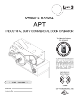
L 3 ogic OWNER'S MANUAL APT INDUSTRIAL DUTY COMMERCIAL DOOR OPERATOR This Operator Features the Enhanced INTENAN MA E M E C AL 2 YEAR WARRANTY Serial # Box of cycles/months is reached or when the operator requires immediate service. Radio Receiver Built on Board 315MHz NOT FOR RESIDENTIAL USE - LiftMaster APT | APT LOGIC 3 Manual - Page 2
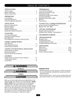
• BEFORE attempting to install, operate or maintain the operator, you must read and fully understand this manual and follow all safety instructions. • DO NOT attempt repair or service of your commercial door and WARNING gate operator unless you are an Authorized Service Technician. When you see - LiftMaster APT | APT LOGIC 3 Manual - Page 3
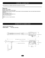
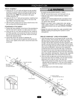
OWNER'S MANUAL AND CAUTION LABELS HARDWARE BOX (INCLUDES FASTENERS, TRACK SPACERS, DOOR ARM ASSEMBLY, FRONT IDLER AND HEADER MOUNTING BRACKET) AUTO RECONNECT TROLLEY 3-BUTTON CONTROL STATION WITH LED TROLLEY DRIVE CHAIN #48 NOTE: The tracks are shipped separately. OPERATOR DIMENSIONS WEIGHTS - LiftMaster APT | APT LOGIC 3 Manual - Page 4
and auxiliary devices to open and close with open override. See pages 16 and 17 for optional wiring types and operating modes. LIMIT ADJUST Linear and oil impregnated. SAFETY DISCONNECT Quick disconnect door arm for emergency manual door operation. SAFETY PHOTO EYES (Optional CPS-L): Through - LiftMaster APT | APT LOGIC 3 Manual - Page 5
below. 3. Slide the trolley carriage onto the track so that the hole of the door arm faces the front (towards door). POWERHEAD ATTACHMENT 1. Position the track assembly on the frame of the powerhead so that the motor side of operator is in back (away from door ). 2. Using (2) 3/8"-16 x 3/4" bolts - LiftMaster APT | APT LOGIC 3 Manual - Page 6
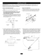
mounting brackets to ensure adequate support of mounting pad. Using suitable hardware, mount the (U-shaped) front header bracket to the pad. 4. Raise the operator to a horizontal position above the guide rails and temporarily secure with a suitable rope, chain, or support from the floor. Open door - LiftMaster APT | APT LOGIC 3 Manual - Page 7
To avoid possible SERIOUS INJURY from a falling operator, CAUTION fasten it SECURELY to structural supports of the garage. Concrete anchors MUST be used if installing ANY brackets into masonry. STRAIGHT ARM ATTACHMENT 1. Fully close the door and move the trolley slider to within 2" (5.08 cm) of the - LiftMaster APT | APT LOGIC 3 Manual - Page 8
close limit nut so that the limit switch is engaged as door fully seats at the floor. WARNING To avoid SERIOUS PERSONAL INJURY or DEATH from electrocution, disconnect electric power BEFORE manually moving limit nuts. SAFETY (Aux. Close) Limit Switch CLOSE Limit Switch CLOSE OPEN 8 OPEN Limit - LiftMaster APT | APT LOGIC 3 Manual - Page 9
OPERATOR The door should be in the fully closed position, if possible. Pull down on the emergency release handle and raise or lower the door manually. TO RECONNECT DOOR ARM TO TROLLEY The trolley will reconnect on the next UP or DOWN operation, either manually or by using the door control or remote - LiftMaster APT | APT LOGIC 3 Manual - Page 10
. Replace brake open position when closing or stops the door when opening. 1. Remove cotterpin from nut on the clutch shaft. 2. Back off clutch nut until there is very little tension on the clutch spring. 3. Tighten clutch nut gradually until there is just enough tension to permit the operator - LiftMaster APT | APT LOGIC 3 Manual - Page 11
and secured, at that time the unit may be returned to service. • Disconnect power at the fuse box BEFORE proceeding. Operator MUST be properly grounded and connected in accordance with local electrical codes. The operator should be on a separate fused line of adequate capacity. • ALL electrical - LiftMaster APT | APT LOGIC 3 Manual - Page 12
WIRING CONNECTIONS On all models a radio terminal bracket marked R1 R2 R3 is located on the outside of the electrical enclosure. In B2 mode the operator will then open a fully closed door, close a fully open door, stop an opening door, and reverse a closing door from the radio remote. In TS control - LiftMaster APT | APT LOGIC 3 Manual - Page 13
(24V DC only) CPS-L & CPS-LN4 R3 R2 R1 Sensing Edge Timer Defeat Switch Maintenance Alert LED (RD) (WH) Open Close Stop Open/Close Single Button OPEN CLOSE STOP 3-Button Station Remove Jumper To Install External Interlock Single Phase Power Wiring Line Power 115 Vac Single Phase Hot - LiftMaster APT | APT LOGIC 3 Manual - Page 14
right hand models and all GH and J models. CPS-L & CPS-LN4 Sensing Edge Hoist Interlock When Present TMR DEF SWITCH (YE) (BL) Maintenance Alert LED (RD) (WH) Open Close Stop OPEN CLOSE STOP 3-Button Station Open/Close Single Button Remove Jumper To Install External Door Interlock MAS - LiftMaster APT | APT LOGIC 3 Manual - Page 15
CMN 11 SINGLE PHASE CONTACTOR/3 PH MOTOR DIRECTION SLS D26 D16 CLS D27 4 D23 EYES D15 P7 MRT MID TIMER D1 EDGE D22 OPEN D2Ø TIMER RADIO 1 2 3 ENABLE D36 CLOSE D21 RELAY A C77 C73 L1 L5 P6 RELAY B D35 T E2 D1 STOP D13 TS FSTS DIAG C2 B2 FAILSAFE SBC PROG (B2 - LiftMaster APT | APT LOGIC 3 Manual - Page 16
, set the operators open and close limits. LEDs Remote Control. D1 Constant pressure to open and close with wiring for sensing device to stop. Compatible with 2-Button Station. E2 Momentary contact to open with override and constant pressure to close. Release of close button will cause door - LiftMaster APT | APT LOGIC 3 Manual - Page 17
Station, 1-Button Station and 1 & 3 Button Remote Control. (NOTE: Requires Optional self monitoring photo eyes to operate.) T Momentary contact to open, close, and stop, with open override and Timer To Close. Every device that causes the door to open, except a reversing device, activates the - LiftMaster APT | APT LOGIC 3 Manual - Page 18
not supported with D1 and E2 failsafe wiring modes. NOTE: Requires self-monitoring photo eyes when using constant pressure to close (wiring C2, D1 and E2 ). SINGLE BUTTON CONTROL (SBC) REMOTE This function programs a remote as a wireless single button control. In B2 mode, operation is OPEN / STOP - LiftMaster APT | APT LOGIC 3 Manual - Page 19
PROGRAMMING Your 315MHz Security✚® or dip switch remote control can be programmed to operate as a 3-button wireless control station: the large button will open the door, the middle button will close the door, and the third button will stop the door's movement. You may set up this feature as follows - LiftMaster APT | APT LOGIC 3 Manual - Page 20
27 to diagnose problem. Example: A door is installed with 30,000 cycle springs and has an annual service contract. To set the MAS, turn selector dial to PROGRAM, press MAS button, press the STOP button to clear the memory and then press the OPEN button 6 times (30,000 cycles) and close 4 times (12 - LiftMaster APT | APT LOGIC 3 Manual - Page 21
Manually (Method 1): SELECTOR DIAL 1. Close the door. 2. Turn the selector dial to PROGRAM. 3. Press the TIMER button on the logic logic board. 4. Press the STOP button to clear the timer. 5. Press the OPEN button for every 5 seconds the operator should wait before attempting to close the door - LiftMaster APT | APT LOGIC 3 Manual - Page 22
15 seconds after a truck enters a garage. To program the Timer to Close, turn the selector dial to PROGRAM, press the TIMER button until the TIMER LED blinks, press the OPEN button and wait until the door reaches the open position, wait for the truck to pass through, count 15 seconds and then press - LiftMaster APT | APT LOGIC 3 Manual - Page 23
seconds. Benefit: If the operator does not meet its open or close limit within the set time it will stop, limiting damage to the door and operator. To Program: NOTE: The default setting for the MRT is 90 seconds. In the event the application requires the MRT be manually learned for a longer duration - LiftMaster APT | APT LOGIC 3 Manual - Page 24
Timer to close = 0 Manual Disconnect Check and operate operation. • Do not lubricate clutch or V-belt. $ Repeat ALL procedures. " Inspect and service whenever a malfunction is observed or suspected. HOW TO ORDER REPAIR PARTS OUR LARGE SERVICE ORGANIZATION SPANS AMERICA Installation and service - LiftMaster APT | APT LOGIC 3 Manual - Page 25
. The following chart should assist in verifying the operator is functioning properly. Turn the selector dial to DIAGNOSTIC to keep the door from moving while troubleshooting. LED Power Stop Open COLOR Green Green Yellow Close Yellow Eyes Green Timer Defeat OLS CLS SLS Edge Mid Stop Timer - LiftMaster APT | APT LOGIC 3 Manual - Page 26
when operator is running. Check for foreign matter blocking optical lens. ➤ Replace RPM sensor. THE DOOR WILL MOVE MOST OF THE WAY TOWARDS A LIMIT THEN STOP. AN EXTRA OPEN OR CLOSE COMMAND IS ABLE TO GET DOOR TO COMPLETE CYCLE The Maximum Run Timer is not set correctly ➤ Manually reprogram - LiftMaster APT | APT LOGIC 3 Manual - Page 27
troubleshoot some problems with the operator. If the MAS LED is flashing on and off rapidly, the Maintenance Alert System has been triggered and the schedule operator service or months) None normal operation E2 No RPM input during opening or closing The door only responds to constant pressure - LiftMaster APT | APT LOGIC 3 Manual - Page 28
be learned R6 Cannot close via constant pressure in C2, D1 or E2 modes. DISPLAY POSSIBLE PROBLEM CORRECTION Quick Flash Unlearned remote A user tries to use a remote, but the RADIO LED only flashes briefly and there is no response from the operator. Try re-learning the remote (page 18). No - LiftMaster APT | APT LOGIC 3 Manual - Page 29
This page intentionally left blank. 29 - LiftMaster APT | APT LOGIC 3 Manual - Page 30
ELECTRICAL BOX 6 5 9 10 4 7 2 3 K2 (K72-12515-1) 11 8 1 K1 (K72-10047) 30 - LiftMaster APT | APT LOGIC 3 Manual - Page 31
ELECTRICAL BOX LOGIC (VER 3.0) For replacement of electrical box, motor or brake components be sure to match model number of your unit to kit number below to ensure proper voltage requirements. SERVICE KITS ITEM K1 K2 PART # K72-10047 K72-12515-1 DESCRIPTION Limit shaft kit Complete with: Limit - LiftMaster APT | APT LOGIC 3 Manual - Page 32
MODEL APT 22 23 21 K4 (K75-13074) 12 15 11 18 5 19 16 3 10 8 5 6 9 7 2 20 24 Drive Chain K3 (K72-13059) 14 17 K5 (K72-13058) 12 13 6 5 K2 (K72-13057) 11 5 4 25 K1 (71-AB120) 1 32 - LiftMaster APT | APT LOGIC 3 Manual - Page 33
REPAIR PARTS KITS - MODEL APT ITEM PART # K1 71-AB120 SERVICE KITS DESCRIPTION Brake kit - 115 Volt models Complete with: Brake solenoid cover, brake release lever, brake disk, spring cup, studs, compression springs, brake solenoid, spacers, mounting plate, pressure plate, feather key and conduit. - LiftMaster APT | APT LOGIC 3 Manual - Page 34
OPERATOR NOTES 34 - LiftMaster APT | APT LOGIC 3 Manual - Page 35
OPERATOR NOTES 35 - LiftMaster APT | APT LOGIC 3 Manual - Page 36
Door Operator. 3 BUTTON STATION OR 3 POSITION KEYSWITCH WITH SPRING RETURN TO CENTER AND STOP BUTTON STANDARD 2 OR MORE KEY LOCKOUT 10 7 6 4 5 10 7 6 4 5 10 7 6 4 5 (RED) Maintenance Alert LED (WHITE) Open Close Stop (RED) Maintenance Alert LED (WHITE) Open Close Stop Open Close
-
 1
1 -
 2
2 -
 3
3 -
 4
4 -
 5
5 -
 6
6 -
 7
7 -
8
-
9
-
10
-
11
-
12
-
13
-
14
-
15
-
16
-
17
-
18
-
19
-
20
-
21
-
22
-
23
-
24
-
25
-
26
-
27
-
28
-
29
-
30
-
31
-
32
-
33
-
34
-
35
-
36
 |
 |
O W N E R ’ S M A N U A L
APT
INDUSTRIAL DUTY COMMERCIAL DOOR OPERATOR
ogic
L
3
NOT FOR RESIDENTIAL USE
A
L
E
R
T
S
Y
S
T
E
M
M
A
I
N
T
E
N
A
N
C
E
PATENT PENDING
The Maintenance Alert System™ allows the
installer to set an internal Maintenance
Cycle Counter. The Logic 3 operator
incorporates a self-diagnostic feature built
into the (MAS) Maintenance Alert System
LED. An LED on the 3-button station will
signal
when
the
set
number
of
cycles/months is reached or when the
operator requires immediate service.
This Operator Features
the Enhanced
Radio Receiver
Built on Board
Serial # Box
Installation Date
2
YEAR
WARRANTY
315MHz