LiftMaster APT APT LOGIC 3 Manual - Page 6
Installation - ats opener
 |
View all LiftMaster APT manuals
Add to My Manuals
Save this manual to your list of manuals |
Page 6 highlights
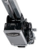
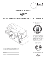
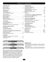
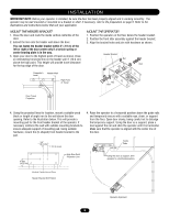
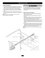
I N S TA L L AT I O N IMPORTANT NOTE: Before your operator is installed, be sure the door has been properly aligned and is working smoothly. The operator may be wall mounted or mounted on a bracket or shelf. If necessary, refer to the preparation on page 5. Refer to the illustrations and instructions below that suit your application. MOUNT THE HEADER BRACKET 1. Close the door and mark the inside vertical centerline of the door. 2. Extend the line onto the header wall above the door. You can fasten the header bracket within 2' (.61 m) of the left or right of the door center only if a torsion spring or center bearing plate is in the way. 3. Open your door to the highest point of travel as shown. Draw an intersecting horizontal line on the header wall 4" (10.2 cm) above the high point. This height will provide travel clearance for the top edge of the door. MOUNT THE OPERATOR 1. Position the operator on the floor below the header bracket. 2. Position the front idler assembly against the header bracket. 3. Align the bracket holes and join with hardware as shown. Header Bracket Nut Bolt Carpenterʼs Level Header Wall High Point of Travel Nut Bolt Door Travel Projection 4. Using the projected lines for location, mount a suitable wood block or length of angle iron to the wall above the door opening. Refer to the illustration below. This will provide a mounting pad for the front header bracket of the operator. If necessary reinforce the wall with suitable mounting brackets to ensure adequate support of mounting pad. Using suitable hardware, mount the (U-shaped) front header bracket to the pad. 4. Raise the operator to a horizontal position above the guide rails and temporarily secure with a suitable rope, chain, or support from the floor. Open door slowly, being careful not to dislodge the temporary support. Using the door as a support, place a level against the rail and shim the operator until it is horizontal. Make sure that the operator is aligned with the center line of the door. 3.5" (8.9 cm) 1.75" (4.5 cm) Guide Rails 4" Min. (10.2 cm) High Rise Point Projection Line Using the door as support, shim operator to a horizontal position. Vertical Center Line of Door Header Bracket Drill Pattern Operator Alignment 6
-
 1
1 -
 2
2 -
 3
3 -
 4
4 -
 5
5 -
 6
6 -
 7
7 -
 8
8 -
 9
9 -
 10
10 -
 11
11 -
 12
12 -
13
-
14
-
15
-
16
-
17
-
18
-
19
-
20
-
21
-
22
-
23
-
24
-
25
-
26
-
27
-
28
-
29
-
30
-
31
-
32
-
33
-
34
-
35
-
36
 |
 |