LiftMaster APT APT LOGIC 3 Manual - Page 19
Your 315MHz Security
 |
View all LiftMaster APT manuals
Add to My Manuals
Save this manual to your list of manuals |
Page 19 highlights
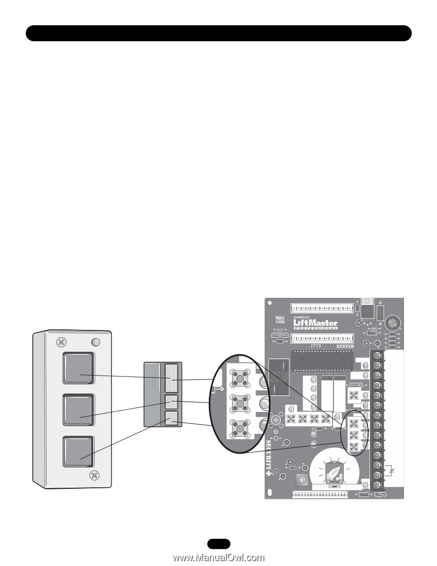
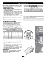
PROGRAMMING Your 315MHz Security✚® or dip switch remote control can be programmed to operate as a 3-button wireless control station: the large button will open the door, the middle button will close the door, and the third button will stop the door's movement. You may set up this feature as follows: 1. To enter programming press the RADIO button on the logic board (the RADIO LED will light). 2. To program the OPEN button to a remote control press the OPEN button on the logic board. The RADIO LED will flash and then stay on solid. Then press the corresponding button on the remote control. The RADIO LED on the logic board will flash, this confirms that the remote control has been programmed. (By programming the remote you use 1 channel of the 23 channels on the radio receiver.) 3. To program the CLOSE button to a remote control press the CLOSE button on the logic board. The RADIO LED will flash and then stay on solid. Then press the corresponding button on the remote control. The RADIO LED on the logic board will flash, this confirms that the remote control has been programmed. (By programming the remote you use 1 channel of the 23 channels on the radio receiver.) 4. To program the STOP button to a remote control press the STOP button on the logic board. The RADIO LED will flash and then stay on solid. Then press the corresponding button on the remote control. The RADIO LED on the logic board will flash, this confirms that the remote control has been programmed. (By programming the remote you use 1 channel of the 23 channels on the radio receiver.) 5. After learning remote controls press the RADIO button on the logic board (LED will turn off). NOTE: If no activity within 30 seconds the radio will automatically exit programming mode. OPEN Open CLOSE Close Stop STOP R31 U7 D8 U1 Ø14LGØ657-A Ø14GPØ657-A P4 C3Ø E1 C18 R29 C11 D3Ø2 X1 P1Ø C17 C25 D1 EDGE K3 D22 OPEN D2Ø POWER OLS J1 D25 J3ØØ D19 TIMER DEFEAT R8 D17 SINGLE PHASE CONTACTOR/3 PH REV STD CLOSE STOP D21 D13 P7 C54 C71 C78 ® MID D24 MAS D28 MOTOR DIRECTION D16 RADIO SLS D26 CLS D27 MRT MID TIMER 1 2 3 D36 RELAY A 4 D23 EYES D15 D1 EDGE D22 OPEN D2Ø TIMER ENABLE CLOSE D21 C77 C73 RELAY B D35 T E2 STOP D13 TS FSTS L1 L5 P6 D1 DIAG C2 B2 FAILSAFE SBC PROG (B2 C2 D1 E2) S8 NON FAILSAFE D14 P1 D34 D31 D7 D6 D5 D4 24V AC 14 24V AC 13 TIMER DEFEAT 12 CMN 11 MAS 10 EYES 9 EDGE 8 OPEN 7 CLOSE 6 STOP 5 CMN 4 3 2 SBC 1 F1 19
-
 1
1 -
2
-
3
-
4
-
5
-
6
-
7
-
8
-
9
-
10
-
11
-
12
-
13
-
 14
14 -
 15
15 -
 16
16 -
 17
17 -
 18
18 -
 19
19 -
 20
20 -
 21
21 -
 22
22 -
 23
23 -
 24
24 -
25
-
26
-
27
-
28
-
29
-
30
-
31
-
32
-
33
-
34
-
35
-
36
 |
 |