LiftMaster APT APT LOGIC 3 Manual - Page 2

Warning, Caution - operator

Page 2 highlights

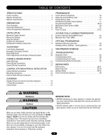
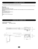
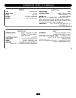
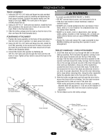
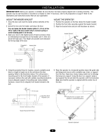
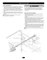
TABLE OF CONTENTS SPECIFICATIONS Carton Inventory 3 Operator Dimensions 3 Operator Specifications 4 PREPARATION Track Assembly 5 Powerhead Attachment 5 Trolley Carriage/Chain Attachment 5 INSTALLATION Mount the Header Bracket 6 Mount the Operator 6 Hang the Operator 7 Straight Arm Attachment 7 Entrapment Protection Accessories 8 ADJUSTMENT Limit Switch Adjustment 8 Emergency Disconnect System 9 Brake Adjustment 10 Clutch Adjustment and Auxiliary Reversal System 10 POWER & GROUND WIRING Safety Warnings 11 Power Wiring Connections 11 Ground Wiring Connections 11 CONTROL STATION WIRING & INSTALLATION Control Wiring Connections 12 Mounting Instructions 12 External Radio Wiring Connections 12 DIAGRAMS Standard Power & Control Connection Diagrams 13 1 Phase Wiring Diagram 14 Control Board 15 PROGRAMMING Control Board Pushbuttons 16 Determine and Set Wiring Type 16 Failsafe Wiring Types 17 Self-Monitoring Safety Device Options 17 Programming Remotes 18-19 Maintenance Alert System (MAS 20 Mid Stop 21 Timer To Close 21-22 AUTOMATICALLY LEARNED PROGRAMMING Auxiliary Reversal System/RPM Sensor 22 Maximum Run Timer (MRT 23 OPTIONAL PROGRAMMING Red/Green Warning Light Card 23 Resetting Factory Defaults - Clearing Memory 24 MAINTENANCE SCHEDULE 24 TROUBLESHOOTING Diagnostic Chart 25 Troubleshooting Guide 26 Troubleshooting Error Codes 27 Troubleshooting Radio Functionality 28 REPAIR PARTS Electrical Box 30-31 Repair Parts Kits 32-33 Operator Notes 34-35 Control Connection Diagram 36 WARNING Mechanical WCAARUNTIIONNG Electrical CWAAURTNIOINNG WARNING IMPORTANT NOTES: WWAARRNNIINNGG • BEFORE attempting to install, operate or maintain the operator, you must read and fully understand this manual and follow all safety instructions. • DO NOT attempt repair or service of your commercial door and WARNING gate operator unless you are an Authorized Service Technician. When you see these Safety Symbols and Signal Words on the following pages, they will alert you to the possibility of serious injury or death if you do not comply with the warnings that accompany them. The hazard may come from something mechanical or from electric shock. Read the warnings carefully. When you see this Signal Word on the following pages, it will alert you to the possibility of damage to your door and/or the door operator if you do not comply with the cautionary statements that accompany it. Read them carefully. 2

  • 1
  • 2
  • 3
  • 4
  • 5
  • 6
  • 7
  • 8
  • 9
  • 10
  • 11
  • 12
  • 13
  • 14
  • 15
  • 16
  • 17
  • 18
  • 19
  • 20
  • 21
  • 22
  • 23
  • 24
  • 25
  • 26
  • 27
  • 28
  • 29
  • 30
  • 31
  • 32
  • 33
  • 34
  • 35
  • 36

2
TABLE OF CONTENTS
SPECIFICATIONS
Carton Inventory . . . . . . . . . . . . . . . . . . . . . . . . . . . . . . . . . . . . .3
Operator Dimensions . . . . . . . . . . . . . . . . . . . . . . . . . . . . . . . . . .3
Operator Specifications . . . . . . . . . . . . . . . . . . . . . . . . . . . . . . . .4
PREPARATION
Track Assembly . . . . . . . . . . . . . . . . . . . . . . . . . . . . . . . . . . . . . .5
Powerhead Attachment . . . . . . . . . . . . . . . . . . . . . . . . . . . . . . . .5
Trolley Carriage/Chain Attachment . . . . . . . . . . . . . . . . . . . . . . . .5
INSTALLATION
Mount the Header Bracket . . . . . . . . . . . . . . . . . . . . . . . . . . . . . .6
Mount the Operator . . . . . . . . . . . . . . . . . . . . . . . . . . . . . . . . . . .6
Hang the Operator . . . . . . . . . . . . . . . . . . . . . . . . . . . . . . . . . . . .7
Straight Arm Attachment . . . . . . . . . . . . . . . . . . . . . . . . . . . . . . .7
Entrapment Protection Accessories . . . . . . . . . . . . . . . . . . . . . . .8
ADJUSTMENT
Limit Switch Adjustment . . . . . . . . . . . . . . . . . . . . . . . . . . . . . . .8
Emergency Disconnect System . . . . . . . . . . . . . . . . . . . . . . . . . .9
Brake Adjustment
. . . . . . . . . . . . . . . . . . . . . . . . . . . . . . . . . . .10
Clutch Adjustment and Auxiliary Reversal System
. . . . . . . . . .10
POWER & GROUND WIRING
Safety Warnings
. . . . . . . . . . . . . . . . . . . . . . . . . . . . . . . . . . . .11
Power Wiring Connections
. . . . . . . . . . . . . . . . . . . . . . . . . . . .11
Ground Wiring Connections
. . . . . . . . . . . . . . . . . . . . . . . . . . .11
CONTROL STATION WIRING & INSTALLATION
Control Wiring Connections
. . . . . . . . . . . . . . . . . . . . . . . . . . .12
Mounting Instructions . . . . . . . . . . . . . . . . . . . . . . . . . . . . . . . .12
External Radio Wiring Connections . . . . . . . . . . . . . . . . . . . . . .12
DIAGRAMS
Standard Power & Control Connection Diagrams . . . . . . . . . . .13
1 Phase Wiring Diagram . . . . . . . . . . . . . . . . . . . . . . . . . . . . . .14
Control Board
. . . . . . . . . . . . . . . . . . . . . . . . . . . . . . . . . . . . . .15
PROGRAMMING
Control Board Pushbuttons . . . . . . . . . . . . . . . . . . . . . . . . . . . .16
Determine and Set Wiring Type . . . . . . . . . . . . . . . . . . . . . . . . .16
Failsafe Wiring Types . . . . . . . . . . . . . . . . . . . . . . . . . . . . . . . . .17
Self-Monitoring Safety Device Options . . . . . . . . . . . . . . . . . . .17
Programming Remotes
. . . . . . . . . . . . . . . . . . . . . . . . . . . .18-19
Maintenance Alert System (MAS) . . . . . . . . . . . . . . . . . . . . . . .20
Mid Stop . . . . . . . . . . . . . . . . . . . . . . . . . . . . . . . . . . . . . . . . . .21
Timer To Close . . . . . . . . . . . . . . . . . . . . . . . . . . . . . . . . . . .21-22
AUTOMATICALLY LEARNED PROGRAMMING
Auxiliary Reversal System/RPM Sensor
. . . . . . . . . . . . . . . . . .22
Maximum Run Timer (MRT) . . . . . . . . . . . . . . . . . . . . . . . . . . .23
OPTIONAL PROGRAMMING
Red/Green Warning Light Card . . . . . . . . . . . . . . . . . . . . . . . . .23
Resetting Factory Defaults - Clearing Memory
. . . . . . . . . . . . .24
MAINTENANCE SCHEDULE
. . . . . . . . . . . . . . . . . . . . . . . .24
TROUBLESHOOTING
Diagnostic Chart
. . . . . . . . . . . . . . . . . . . . . . . . . . . . . . . . . . . .25
Troubleshooting Guide . . . . . . . . . . . . . . . . . . . . . . . . . . . . . . . .26
Troubleshooting Error Codes . . . . . . . . . . . . . . . . . . . . . . . . . . .27
Troubleshooting Radio Functionality . . . . . . . . . . . . . . . . . . . . .28
REPAIR PARTS
Electrical Box . . . . . . . . . . . . . . . . . . . . . . . . . . . . . . . . . . . .30-31
Repair Parts Kits
. . . . . . . . . . . . . . . . . . . . . . . . . . . . . . . . .32-33
Operator Notes . . . . . . . . . . . . . . . . . . . . . . . . . . . . . . . . . . .34-35
Control Connection Diagram . . . . . . . . . . . . . . . . . . . . . . . . . . .36
When you see these Safety Symbols and Signal Words on the
following pages, they will alert you to the possibility of
serious
injury
or
death
if you do not comply with the warnings that
accompany them. The hazard may come from something
mechanical or from electric shock. Read the warnings carefully.
When you see this Signal Word on the following pages, it will
alert you to the possibility of damage to your door and/or the
door operator if you do not comply with the cautionary
statements that accompany it. Read them carefully.
Mechanical
Electrical
WARNING
WARNING
CAUTION
IMPORTANT NOTES:
• BEFORE attempting to install, operate or maintain the operator,
you must read and fully understand this manual and follow all
safety instructions.
• DO NOT attempt repair or service of your commercial door and
gate operator unless you are an Authorized Service Technician.