LiftMaster APT APT LOGIC 3 Manual - Page 5
Warning - trolley
 |
View all LiftMaster APT manuals
Add to My Manuals
Save this manual to your list of manuals |
Page 5 highlights
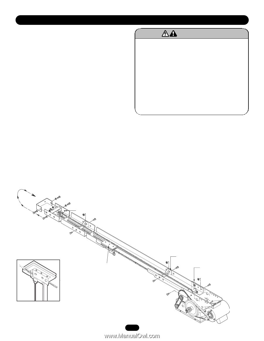
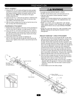
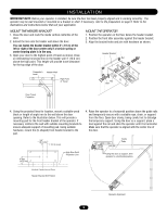
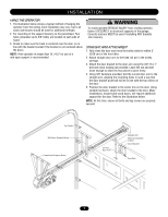
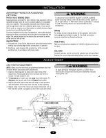
WARNING PREPARATION WARNING CAUTION TRACK ASSEMBLY 1. Using the 3/8"-16 x 3/4" bolts and flange hex nuts provided, assemble the operator track by installing and tightening the track spacer brackets. Position the spacers evenly over the length of the track. NOTE: The nylon pad on the spacer bracket should face up. 2. Using (2) 3/8"-16 x 1" bolts and lock washers, install the front idler assembly to the second set of holes of one end of the track. Refer to the illustration below. 3. Slide the trolley carriage onto the track so that the hole of the door arm faces the front (towards door). POWERHEAD ATTACHMENT 1. Position the track assembly on the frame of the powerhead so that the motor side of operator is in back (away from door ). 2. Using (2) 3/8"-16 x 3/4" bolts and flange hex nuts, install the front idler assembly to the second set of holes of one end of the track. Be sure the take-up bolt faces toward end of track. Refer to the illustration below. 3. Connect the track to the operator by fastening (2) 3/8"-16 x 3/4" bolts and nuts through the frame and the end holes in track. Tighten all four bolts to secure the track to the powerhead. Reel Chain Around Idler and over Spacer Brackets Front Idler Assembly WARNING To prevent possible SERIOUS INJURY or DEATH: • DO NOT connect electric power until instructed to do so. • If the door lock needs to remain functional, install an interlock switch. • ALWAYS call a trained professional door serviceman if door binds, sticks or is out of balance. An unbalanced door may not reverse when required. • NEVER try to loosen, move or adjust doors, door springs, cables, pulleys, brackets or their hardware, ALL of which are under extreme tension and can cause SERIOUS PERSONAL INJURY. • Disable ALL locks and remove ALL ropes connected to door BEFORE installing and operating door operator to avoid entanglement. TROLLEY CARRIAGE / CHAIN ATTACHMENT 1. Uncoil the chain and run it up through the idler on the chain take-up assembly. Pull it towards the operator running it over the nylon spacer brackets and over the top of the trolley carriage. Pull the chain around the final drive sprocket on the operator and back toward the trolley carriage. Pull the release clip on the carriage and push one end of the chain through the chain slot (see illustration). Using one of the masterlinks, connect the drive link to one end of the chain. Pull the drive link toward the free end of the chain and determine where to cut chain for proper adjustment. Be sure the chain tensioning bolt is loose before removing links. Using the other masterlink fasten the adjusted chain to the free end of the drive link. 2. Slide the trolley carriage back and forth past the drive link to assure that there will be no binding. Turn the chain tensioner adjustment bolt to take out most of the chain lack. • With trolley positioned at either end of the track, a properly adjusted chain will sag about 3" (7.62 cm) at the midpoint. If necessary, remove links from the chain to achieve proper adjustment. 3. Tie the release cord to the trolley carriage. Trolley Assembly Trolley Carriage Spacer Bracket (mounted nylon pad side up) L - Slot 5
-
 1
1 -
 2
2 -
 3
3 -
 4
4 -
 5
5 -
 6
6 -
 7
7 -
 8
8 -
 9
9 -
 10
10 -
 11
11 -
12
-
13
-
14
-
15
-
16
-
17
-
18
-
19
-
20
-
21
-
22
-
23
-
24
-
25
-
26
-
27
-
28
-
29
-
30
-
31
-
32
-
33
-
34
-
35
-
36
 |
 |