Marantz NR1501 NR1501 User Manual - English - Page 13
Connecting Audio Components
 |
View all Marantz NR1501 manuals
Add to My Manuals
Save this manual to your list of manuals |
Page 13 highlights
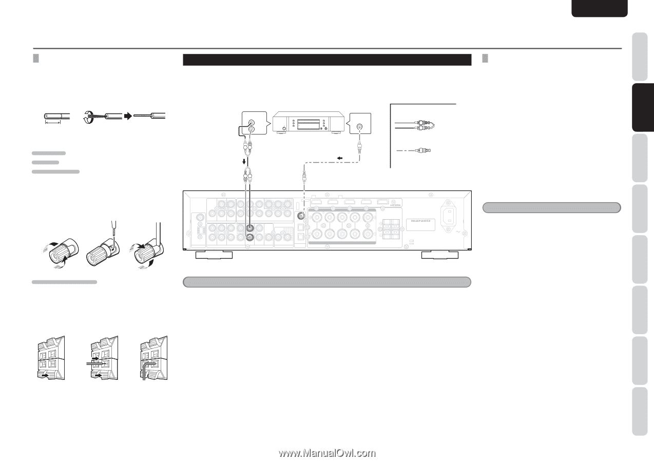
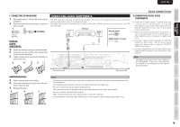
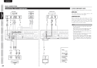
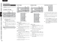
CONNECTIONS FUNCTIONS NAMES AND BASIC BASIC OPERATION ENGLISH CONNECTING SPEAKER WIRE 1. Strip away approx. 10 mm (3/8 inch) of wire insulation. 2. Twist the bared wire ends tight, to prevent short circuits. 1. 2. 10 mm (3/8 inch) FRONT R/L CENTER SURROUND R/L 3. Loosen the knob by turning it counterclockwise. 4. Insert the bare part of the wire into the hole in side of each terminal. 5. Tighten the knob by turning it clockwise to secure the wire. 3. 4. 5. CONNECTING AUDIO COMPONENTS The VCR OUT terminals are for recording purposes. The sound of the analog input source component currently selected is output from these terminals. The digital sound, which has been input to the DIGITAL IN or HDMI terminal, is not output from the VCR OUT terminals. OUT L R CD Player DIGITAL OUTPUT Analog Audio LR Digital Audio (coaxial) LR RL MONITOR OUT OUT DVD MONITOR OUT BLU-RAY GAME DVD DSS OUT FM (75Ω) GND AM IN DVD IN DSS VIDEO IN VCR L 3 Y PB/CB PR/CR Y PB/CB PR/CR DSS VCR COMPONENT VIDEO 2 PRE OUT R ANTENNA IN DVD IN DSS IN OUT VCR ANALOG AUDIO IN CD 1 IN AUX 2 SUB WOOFER IN OUT REMOTE CONTROL IN DIGITAL AUDIO MODEL NO. NR1501 R - FRONT - L CENTER R - SURR. - L SPEAKER SYSTEMS : 6-8 OHMS R L SURROUND BACK AC IN BASIC CONNECTIONS CONNECTING DIGITAL AUDIO COMPONENTS • There are 3 digital inputs, 2 coaxial jacks and 1 optical jack, on the rear panel. You can use these jacks to input PCM, Dolby Digital and DTS bitstream signals from a CD, DVD, or other digital source components. • Refer to the instructions for each component. To setup the digital audio format of DVD player, or other digital source's connected to digital input jacks. • Use fiber optical cables (optical) for DIGITAL AUDIO-1,2 input jacks. Use 75 ohms coaxial cables (for digital audio or video) for DIGITAL AUDIO-3 input jacks. • You can designate the input for each digital input/ output jacks according to your component. (See page 20) Note • The digital signal jacks on this unit conform to the EIA standard. If you use a cable that does not conform to this standard, this unit may not function properly. SURROUND BACK R/L 3. Push the lever and hold it down. 4. Insert the twisted ends of the wires into the hole in the terminal. 5. Release the lever. 3. 4. 5. Notes • Do not connect this unit and other components to mains power until all connections between components have been completed. • Insert all plugs and connectors securely. Incomplete connections may make noise. • Be sure to connect the left and right channels properly. Red connectors are for the R (right) channel, and white connectors are for the L (left) channel. • Be sure to connect input and output properly. • Refer to the instructions for each component that is connected to this unit. • Do not bundle the connected cables with the power cord or speaker cables. Doing so may produce noise. ADVANCED CONNECTIONS SETUP ADVANCED OPERATION TROUBLESHOOTING OTHERS 9
-
 1
1 -
2
-
3
-
4
-
5
-
6
-
7
-
 8
8 -
 9
9 -
 10
10 -
 11
11 -
 12
12 -
 13
13 -
 14
14 -
 15
15 -
 16
16 -
 17
17 -
 18
18 -
19
-
20
-
21
-
22
-
23
-
24
-
25
-
26
-
27
-
28
-
29
-
30
-
31
-
32
-
33
-
34
-
35
-
36
-
37
-
38
-
39
-
40
-
41
-
42
-
43
-
44
-
45
-
46
-
47
-
48
-
49
-
50
 |
 |