Marantz SR7300OSE User Guide - Page 12
Rear Panel
 |
View all Marantz SR7300OSE manuals
Add to My Manuals
Save this manual to your list of manuals |
Page 12 highlights
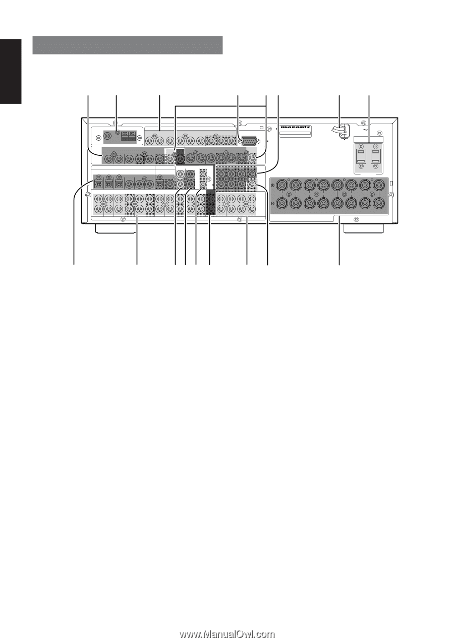
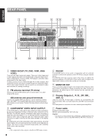
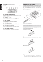
ENGLISH REAR PANEL zx c v bn m, ANTENNA FM (75Ω) VIDEO TV GND AM DVD VCR1 IN OUT COMPONENT VIDEO DVD DSS / VCR2 MONI OUT Y CB / PB CR / PR Y CB / PB CR / PR Y CB / PB CR / PR RS-232C DSS / VCR2 MONI MULTI TV IN OUT OUT OUT DVD VCR1 IN OUT DSS/VCR2 IN OUT S-VIDEO MONI OUT MODEL NO. SR7300 AC IN SERIAL NO. DIGITAL IN 1 2 3 4 TV DVD L VCR1 IN OUT R RC-5 MULTI DC OUT DIGITAL OUT RC L SL 5 6 OPT COAX IN OUT DSS / VCR2 CD TAPE CDR / MD MULTI R SR IN OUT IN OUT IN OUT OUT L SL AUDIO R SR (AUX2) SBL SBR SBL SBR C PRE OUT SW C 7.1CH IN SW R L R L FRONT A FRONT B CENTER SPEAKER SYSTEMS FRONT A OR B, CENTER, SURROUND, SURR. BACK : MINIMUM 6 OHMS FRONT A AND B : MINIMUM 8 OHMS SWITCHED UNSWITCHED 120W 1A MAX 120W 1A MAX AC OUTLET 120V 60HZ R L SURROUND SURROUND BACK ⁄7 ⁄6 ⁄⁄5 ⁄4 3 ⁄2 ⁄1 ⁄0 . z VIDEO IN/OUT (TV, DVD, VCR1, DSS/ VCR2) These are the video inputs and outputs. There are 4 video inputs and 2 video outputs and each one includes both composite video and Svideo configurations. Connect VCRs, DVD players, and other video components to the video inputs. S-video sources can be viewed through the S-video outputs, and composite sources can only be viewed through the composite output. The 2 video output channels can be used to be connected to video tape recorders for making recordings. x FM antenna terminal (75 ohms) Connect an external FM antenna with a coaxial cable, or a cable network FM source. AM antenna and ground terminals Connect the supplied AM loop antenna. Use the terminals marked "AM" and "GND". The supplied AM loop antenna will provide good AM reception in most areas. Position the loop antenna until you hear the best c COMPONENT VIDEO INPUT/OUTPUT If your DVD player or other device has component video connectors, be sure to connect them to these component video connectors on the SR7300. The SR7300 has two component video input connectors to obtain the color information (Y, CB, CR) directly from the recorded DVD signal or other video component and one component video output connector to output it directly into the matrix decoder of the display device. By sending the pure DVD component video signal directly, the DVD signal forgoes the extra processing that normally would degrade the image. The result is vastly increased image quality, with incredibly lifelike colors and crisp detail. Notes: • This component video output is disable to OSD menu system. 8 v RS232C The RS232C port is to be used in conjunction with an external controller to control the operation of the SR7300 by using an external device. The RS232C port may also be used in the future to update the operating software of the SR7300 so that it will be able to support new digital audio formats and the like as they are introduced. b MONITOR OUT This is a monitor output and each one includes both composite video and S-video configurations. When connecting two video monitors or televisions, be aware that the OSD interface can be used with both MONITOR OUT. n Preamp Outputs (L, R, SL, SR, SBL, SBR, C) Jacks for L(front left), R (front right), C (Center), SL (surround left), SR (surround right), SBL (surround back left) and SBR (surround back right). Use these jacks for connection to some external power amplifiers. m Power cable Connect to AC power outlet. SR7300 can be powered by 120 V AC only. Caution: • In order to avoid potential turn-off thumps, anything plugged in here should be powered up BEFORE the SR7300 is turned on.
-
 1
1 -
2
-
3
-
4
-
5
-
6
-
 7
7 -
 8
8 -
 9
9 -
 10
10 -
 11
11 -
 12
12 -
 13
13 -
 14
14 -
 15
15 -
 16
16 -
 17
17 -
18
-
19
-
20
-
21
-
22
-
23
-
24
-
25
-
26
-
27
-
28
-
29
-
30
-
31
-
32
-
33
-
34
-
35
-
36
-
37
-
38
-
39
-
40
-
41
-
42
-
43
-
44
-
45
-
46
-
47
-
48
-
49
-
50
-
51
-
52
-
53
 |
 |