Marantz SR7300OSE User Guide - Page 19
Connecting Speakers
 |
View all Marantz SR7300OSE manuals
Add to My Manuals
Save this manual to your list of manuals |
Page 19 highlights
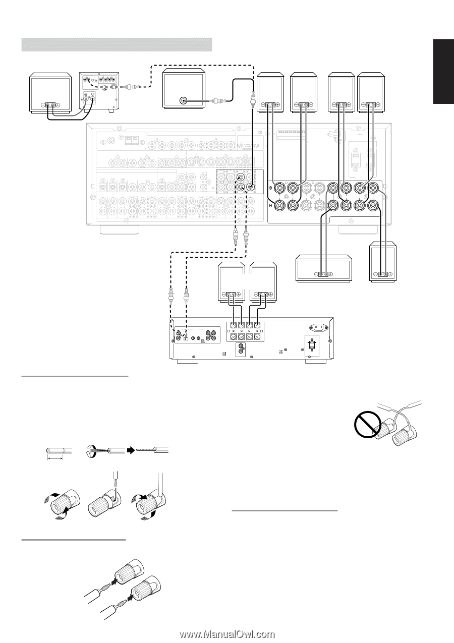
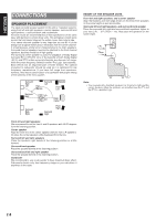
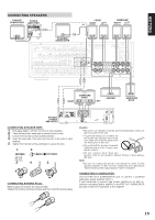
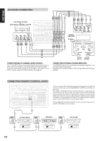
ENGLISH CONNECTING SPEAKERS PASSIVE SUBWOOFER POWER AMPLIFIER INVERT OUTPUT INPUT INPUT LEVEL BTL EXT. CONT. IN MASTER SLAVE REMOTE CONT. MIN MAX VIDEO/ SYSTEM OUT OUT IN +5~13V DC FUSE FRONT RIGHT LEFT or SURROUND RIGHT LEFT SPEAKER SYSTEM MINIMUM 4 OHMS POWERED SUBWOOFER ANTENNA FM (75Ω) VIDEO TV GND AM DVD VCR1 IN OUT COMPONENT VIDEO DVD DSS / VCR2 MONI OUT Y CB / PB CR / PR Y CB / PB CR / PR Y CB / PB CR / PR RS-232C DSS / VCR2 MONI MULTI TV IN OUT OUT OUT DVD VCR1 IN OUT DSS/VCR2 IN OUT S-VIDEO MONI OUT MODEL NO. SR7300 AC IN SERIAL NO. DIGITAL IN RC-5 MULTI DC OUT DIGITAL OUT RC L SL 1 2 3 4 5 6 OPT COAX IN OUT TV DVD VCR1 DSS / VCR2 CD TAPE CDR / MD MULTI R SR IN OUT IN OUT IN OUT IN OUT OUT L SL L R AUDIO R SR (AUX2) SBL C PRE OUT SBR SBL SW C 7.1CH IN SBR SW R L R L FRONT A FRONT B CENTER SPEAKER SYSTEMS FRONT A OR B, CENTER, SURROUND, SURR. BACK : MINIMUM 6 OHMS FRONT A AND B : MINIMUM 8 OHMS SWITCHED UNSWITCHED 120W 1A MAX 120W 1A MAX AC OUTLET 120V 60HZ R L SURROUND SURROUND BACK RIGHT SURROUND BACK LEFT CENTER SURROUND BACK STEREO POWER AMPLIFIER DIRECT INPUT L R LEVEL R L MIN MAX MIN MAX VARIABLE THRU INPUT OUTPUT L R A A R L B B SPEAKER SYSTEMS IN OUT REMOTE CONTROL CONNECTING SPEAKER WIRE 1. Strip away approx. 3/8 inch (10 mm) of wire insulation. 2. Twist the bared wire ends tight to prevent short circuits. 3. Loosen the knob by turning counterclockwise. 4. Insert the bare part of the wire into the hole in the side of each terminal. 5. Tighten the knob by turning clockwise to secure the wire. 1. 2. 3/8 inch (10 mm) 3. 4. 5. CONNECTING BANANA PLUG Banana plug connections are also possible. Tighten the knob by turning clockwise and then insert the banana plug. Caution: • Be sure to use speakers with the specified impedance shown on the rear panel of this unit. • To prevent damage to circuitry, do not let the bare speaker wires touch each other and do not let them touch any metal part of this unit. • Do not touch the speaker terminals when the power is on. It may cause electric shocks. • Do not connect more than one speaker cable to one speaker terminal. Doing so may damage this unit. Note: • Be sure to connect the positive and negative cables for the speaker properly. If they are miss-connected, the signal phase will reversed and the signal quality will be corrupted. CONNECTING A SUBWOOFER Use the PRE OUT SUBWOOFER jack to connect a powered subwoofer (power amplifier built in ). If your subwoofer is passive type (power amplifier is not built in), connect a monaural power amplifier to the PRE OUT SUBWOOFER jack and connect the subwoofer to the amplifier. 15
-
 1
1 -
2
-
3
-
4
-
5
-
6
-
7
-
8
-
9
-
10
-
11
-
12
-
13
-
 14
14 -
 15
15 -
 16
16 -
 17
17 -
 18
18 -
 19
19 -
 20
20 -
 21
21 -
 22
22 -
 23
23 -
 24
24 -
25
-
26
-
27
-
28
-
29
-
30
-
31
-
32
-
33
-
34
-
35
-
36
-
37
-
38
-
39
-
40
-
41
-
42
-
43
-
44
-
45
-
46
-
47
-
48
-
49
-
50
-
51
-
52
-
53
 |
 |