NordicTrack 360 Canadian English Manual
NordicTrack 360 Manual
 |
View all NordicTrack 360 manuals
Add to My Manuals
Save this manual to your list of manuals |
NordicTrack 360 manual content summary:
- NordicTrack 360 | Canadian English Manual - Page 1
, or if parts are damaged or missing, PLEASE CONTACT OUR CUSTOMER SERVICE DEPARTMENT DIRECTLY. CALL TOLL-FREE: 1-888-936-4266 Mon.-Fri., 8:00 until 17:00 ET (excluding holidays) OR E-MAIL US: [email protected] CAUTION Read all precautions and instructions in this manual before using this - NordicTrack 360 | Canadian English Manual - Page 2
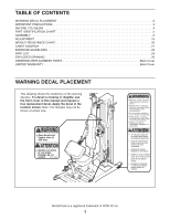
DECAL PLACEMENT 2 IMPORTANT PRECAUTIONS 3 BEFORE YOU BEGIN 4 PART IDENTIFICATION CHART 5 ASSEMBLY 6 ADJUSTMENT 15 WEIGHT RESISTANCE CHART 20 CABLE DIAGRAM 21 EXERCISE GUIDELINES 22 PART LIST 24 EXPLODED DRAWING 26 ORDERING REPLACEMENT PARTS Back Cover LIMITED WARRANTY Back Cover WARNING - NordicTrack 360 | Canadian English Manual - Page 3
important precautions and instructions in this manual and all warnings on your weight system before using your weight sys- tem. away from moving parts. 8. Always wear athletic shoes for foot protection while exercising. 9. The weight system is designed to support a maximum user weight of 300 lbs. - NordicTrack 360 | Canadian English Manual - Page 4
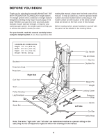
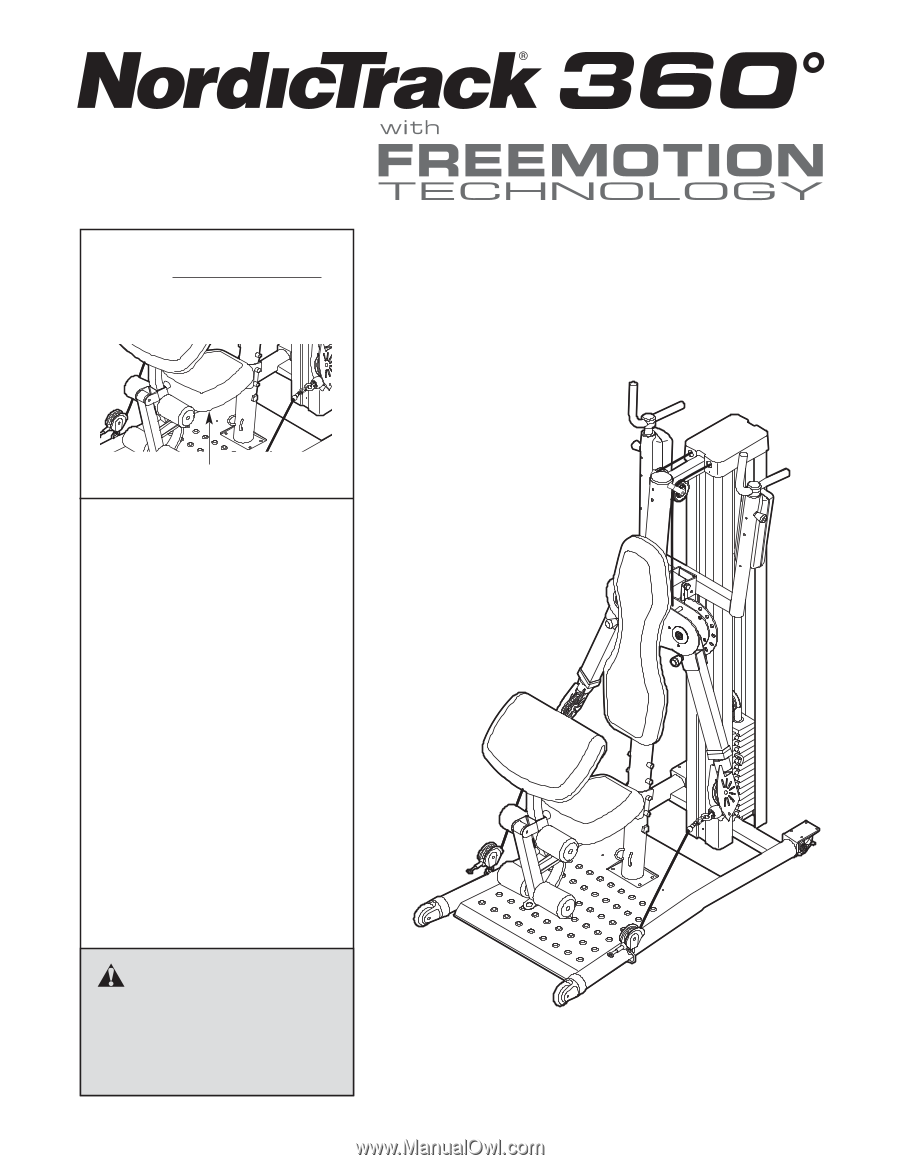
BEFORE YOU BEGIN Thank you for selecting the versatile NordicTrack® 360° WITH FREEMOTION TECHNOLOGY weight system. The weight system offers a selection of weight stations designed to develop every major muscle group of the body. Whether your goal is to tone your body, build dramatic muscle size and - NordicTrack 360 | Canadian English Manual - Page 5
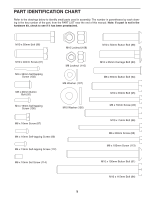
PART IDENTIFICATION CHART Refer to the drawings below to identify small parts used in assembly. The number in parentheses by each drawing is the key number of the part, from the PART LIST near the end of this manual. Note: If a part is not in the hardware kit, check to see if it has been preattached - NordicTrack 360 | Canadian English Manual - Page 6
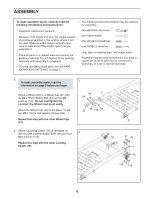
information and instructions: • Assembly requires two persons. • Because of its weight and size, the weight system should be assembled in the location where it will be used. Make sure that there is enough clearance to walk around the weight system as you assemble it. • Place all parts in a cleared - NordicTrack 360 | Canadian English Manual - Page 7
motivation, keep a record of each workout. Write the date, the exercises performed, the resistance used, and the numbers of sets and repetitions completed. Record your weight and key body measurements once a month. To achieve good results, make exercise a regular and enjoyable part of your life. 22 - NordicTrack 360 | Canadian English Manual - Page 8
the Press Arm Cable (66). Use the diagram to make sure that the cable and the cable traps have been assembled correctly. If the cable has not been correctly routed, the weight system will not function properly and damage may occur. The numbers show the correct route for the cable. Make sure - NordicTrack 360 | Canadian English Manual - Page 9
Top Cover (24), make sure that the Cable crosses under the Top Frame (12) and hangs between the Weight Guides (13, 36) while this step is completed. Attach the Top Frame (12) to the Weight Guides (13, 36) with two M10 x 65mm Bolts (95), four M10 Washers (105), two 16mm x 6mm Spacers (11), and - NordicTrack 360 | Canadian English Manual - Page 10
(66) under a 3 1/2" 10 Pulley (43). Attach the Pulley, a Cable Trap (47), and two Finger Guards (48) to the second hole from the top of the Weight Tube (16) with an M10 x 50mm Bolt (96) and an M10 Locknut (108). Make sure that the Cable Trap is ori- ented to hold the - NordicTrack 360 | Canadian English Manual - Page 11
11. Route the Press Arm Cable (66) over a 3 1/2" Pulley (43). Attach the Pulley and a Cable Trap 11 (47) to the Top Frame (12) with an M10 x 40mm Screw (97). Make sure that the Cable Trap is oriented to hold the Cable in the groove of the Pulley. 47 43 97 66 12 12. Route the Press Arm Cable ( - NordicTrack 360 | Canadian English Manual - Page 12
14. Orient the Cable Cover (63) as shown and slide it onto the Press Arm Cable (66). 14 Insert the Press Arm Cable (66) into the Cable Coupler (64) as far as possible. Firmly tighten four M6 x 10mm Set Screws (114) into the Coupler to hold the Cable in place. Slide the Cable Cover (63) over the - NordicTrack 360 | Canadian English Manual - Page 13
17. Attach the Seat (19) to the Seat Frame (4) with two M6 x 16mm Screws (87) and an M6 x 17 85mm Screw (85). Set the Seat Frame (4) onto a set of posts on the Upright (3). 19 4 85 87 18. Attach the Bumper (115) to the Leg Developer (6) with an M4 x 19mm Self-tapping Screw 18 (100). 86 4 - NordicTrack 360 | Canadian English Manual - Page 14
23 22. Attach the Curl Pad (20) to the Curl Post (9) with two M6 x 16mm Screws (87). 22 20 9 87 23. Make sure that all parts are properly tightened before you use the weight system. The use of the remaining parts will be explained in the ADJUSTMENT section, beginning on page 15. 14 - NordicTrack 360 | Canadian English Manual - Page 15
how to get the most benefit from your exercise program. Also, refer to the accompanying exercise guide to see the correct form for each exercise. Properly tighten all parts each time the weight system is used. Replace any worn parts immediately. The weight system can be cleaned with a damp cloth and - NordicTrack 360 | Canadian English Manual - Page 16
off the Upright (3). Set the Seat Frame onto a different set of posts on the Upright. For some exercises, the Seat (19) should be removed from the weight system and stored where it will not interfere with the exercises. 5 3 53 3 19 4 ATTACHING THE CURL PAD To use the Curl Pad (20), insert the Curl - NordicTrack 360 | Canadian English Manual - Page 17
ATTACHING THE PULLEY HOUSINGS The Pulley Housings (54) can be attached to the Upright (3) (leg developer position) or to the Base (1) (squat position or preacher curl position). To attach a Pulley Housing (54), slide the hook on the Pulley Housing onto the bracket at the desired position. Attach the - NordicTrack 360 | Canadian English Manual - Page 18
or to a Housing Cable (not shown), with a Clip (61). For some exercises, an Extension Strap (not shown) should be attached between the Eyehook or the MOVING THE WEIGHT SYSTEM To move the weight system, step on the levers on the Locking Casters (76) to unlock the wheels. Move the weight system to - NordicTrack 360 | Canadian English Manual - Page 19
amount of resistance at each exercise station may vary from the weight setting. Use the WEIGHT RESISTANCE CHART on page 20 to find the approximate amount of resistance. LOCKING THE WEIGHT STACK To lock the weight stack, insert the Lock Pin (78) into the indicated hole in a Weight Guide With Hole (36 - NordicTrack 360 | Canadian English Manual - Page 20
WEIGHT RESISTANCE CHART The chart below shows the approximate weight resistance for the 10-lb. weights. Note: The actual resistance at each station may vary due to differences in individual weight plates and to friction between the cables, pulleys, and weight guides. WEIGHT 1 2 3 4 5 6 7 8 9 10 11 - NordicTrack 360 | Canadian English Manual - Page 21
4. Note: The parts in steps 7, 13, and 14 may be preassembled. If the Press with an M4 x 13mm Self-tapping Screw (112). Insert the Pin into the Dip Arm and the Upright (3). 5. Attach the Weight Guide (13) to the Base (1) with an M10 x 50mm Bolt (96), two M10 5 Washers (105), an 16mm x 6mm Spacer - NordicTrack 360 | Canadian English Manual - Page 22
3. Press the 89mm Round Cap (39) into the Upright (3). 3 39 Insert four M10 x 55mm Carriage Bolts (83) up through the Base (1). Note: Covering the bolt heads with a piece of tape will help hold 3 them in place. Attach the Upright (3) to the Base with the four Bolts and four M10 Locknuts ( - NordicTrack 360 | Canadian English Manual - Page 23
use the copies to schedule and record your strength and aerobic workouts. Scheduling and recording your workouts will help you to make exercise a regular and enjoyable part of your life. Strength Date: Exercise 1. 2. 3. 4. 5. Lbs. Sets Reps Exercise 6. 7. 8. 9. 10. Lbs. Sets Reps Aerobic Date - NordicTrack 360 | Canadian English Manual - Page 24
PART LIST-Model No. 30281.0 R0909A Key No. Qty. 1 1 2 1 3 1 4 1 5 1 6 1 7 1 8 1 9 1 10 2 11 6 12 1 13 1 Adjustment Plate Swivel Arm Weight Weight Pin Weight Bumper Weight Bushing Wheel Cap Wheel Front Dip Cap Rear Dip Cap Dip Arm Bushing Weight Guide With Hole 57mm Round - NordicTrack 360 | Canadian English Manual - Page 25
x 100mm Screw M6 x 10mm Set Screw Bumper Outer Snap Ring M10 Nut 76mm x 76mm Cap Userʼs Manual Exercise Guide Hex Key Note: Specifications are subject to change without notice. For information about ordering replacement parts, see the back cover of this manual. *These parts are not illustrated. 25 - NordicTrack 360 | Canadian English Manual - Page 26
EXPLODED DRAWING A-Model No. 30281.0 R0909A 39 92 25 110 50 91 108 113 43 107 8 89 68 41 40 88 105 42 72 26 11 18 116 105 114 63 66 109 64 117 65 104 75114 11 108 19 20 74 44 74 108 90 80 111 49 3 67 60 108 49 111 90 45 90 84 25 118 49 111 92 53 112 74 108 113 107 4944 - NordicTrack 360 | Canadian English Manual - Page 27
EXPLODED DRAWING B-Model No. 30281.0 R0909A 69 101 57 106 61 57 58 70 57 82 56 55 24 97 97 47 47 43 43 43 47 95 98 46 46 54 108 44 98 71 46 54 46 108 44 71 99 57 59 100 14 100 105 36 77 92 2 99 96 105 92 12 99 43 47 97 97 81 105 108 15 13 99 78 43 48 11 105 96 108 30 16 - NordicTrack 360 | Canadian English Manual - Page 28
replacement part(s) (see the PART LIST and the EXPLODED DRAWING near the end of this manual) LIMITED WARRANTY ICON of Canada, Inc. (ICON) warrants this product to be free from defects in workmanship and material, under normal use and service enjoyment or use, or costs of removal or installation; or
-
 1
1 -
 2
2 -
 3
3 -
 4
4 -
 5
5 -
 6
6 -
 7
7 -
8
-
9
-
10
-
11
-
12
-
13
-
14
-
15
-
16
-
17
-
18
-
19
-
20
-
21
-
22
-
23
-
24
-
25
-
26
-
27
-
28
 |
 |
USERʼS MANUAL
www.nordictrack.com
Serial Number Decal (Under Seat)
Model No. 30281.0
Serial No.
Write the serial number in the
space above for reference.
QUESTIONS?
If you have questions, or if parts
are damaged or missing,
PLEASE
CONTACT OUR CUSTOMER
SERVICE DEPARTMENT
DIRECTLY.
CALL TOLL-FREE:
1-888-936-4266
Mon.–Fri., 8:00 until 17:00 ET
(excluding holidays)
OR E-MAIL US:
CAUTION
Read all precautions and instruc-
tions in this manual before using
this equipment. Keep this manual
for future reference.