NordicTrack 360 Canadian English Manual - Page 6
Assembly - chart
 |
View all NordicTrack 360 manuals
Add to My Manuals
Save this manual to your list of manuals |
Page 6 highlights
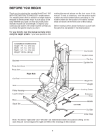
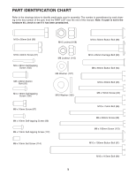
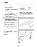
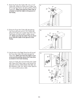
ASSEMBLY To make assembly easier, carefully read the following information and instructions: • Assembly requires two persons. • Because of its weight and size, the weight system should be assembled in the location where it will be used. Make sure that there is enough clearance to walk around the weight system as you assemble it. • Place all parts in a cleared area and remove the packing materials. Do not dispose of the packing materials until assembly is completed. • For help identifying small parts, use the PART IDENTIFICATION CHART on page 5. • The following tools (not included) may be required for assembly: two adjustable wrenches one rubber mallet one standard screwdriver one Phillips screwdriver clear tape or masking tape, and soapy water Assembly may be more convenient if you have a socket set, a set of open-end or closed-end wrenches, or a set of ratchet wrenches. 1. To make assembly easier, read the information on page 5 before you begin. Attach a Wheel (32) to a Wheel Cap (31) with an M8 x 65mm Button Bolt (94) and an M8 Locknut (110). Do not overtighten the Locknut; the Wheel must pivot easily. Attach the Wheel Cap (31) to the Base (1) with two M4 x 16mm Self-tapping Screws (99). Repeat this step with the other Wheel Cap (31). 1 99 1 94 32 31 110 99 2. Attach a Locking Caster (76) to the Base (1) with four M8 x 20mm Button Bolts (92) and four 2 M8 Locknuts (110). 76 Repeat this step with the other Locking Caster (76). 31 92 92 1 76 110 110 6
-
 1
1 -
 2
2 -
 3
3 -
 4
4 -
 5
5 -
 6
6 -
 7
7 -
 8
8 -
 9
9 -
 10
10 -
 11
11 -
 12
12 -
13
-
14
-
15
-
16
-
17
-
18
-
19
-
20
-
21
-
22
-
23
-
24
-
25
-
26
-
27
-
28
 |
 |
