NordicTrack 360 Canadian English Manual - Page 9
See drawing 6a. Note: If the Press Arm
 |
View all NordicTrack 360 manuals
Add to My Manuals
Save this manual to your list of manuals |
Page 9 highlights
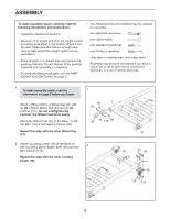
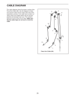
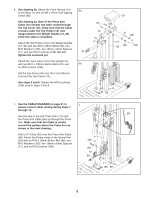
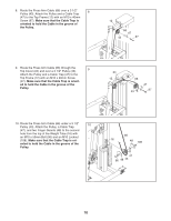
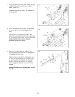
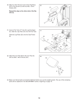
6. See drawing 6b. Attach the Front Shroud (14) to the Base (1) with an M4 x 16mm Self-tapping Screw (99). See drawing 6a. Note: If the Press Arm Cable (not shown) has been routed through the Top Cover (24), make sure that the Cable crosses under the Top Frame (12) and hangs between the Weight Guides (13, 36) while this step is completed. Attach the Top Frame (12) to the Weight Guides (13, 36) with two M10 x 65mm Bolts (95), four M10 Washers (105), two 16mm x 6mm Spacers (11), and two M10 Locknuts (108). Do not tighten the Locknuts yet. Attach the Top Frame (12) to the Upright (3) with two M10 x 100mm Button Bolts (91) and an M10 Locknut (108). Set the Top Cover (24) over the Front Shroud (14) and the Top Frame (12). See steps 3 and 6. Tighten the M10 Locknuts (108) used in steps 3 and 6. 6a 91 6b 24 95 105 12 14 3 108 11 105 13 36 105 108 1 14 99 7. See the CABLE DIAGRAM on page 21 to ensure correct cable routing during steps 7 7 through 14. 66 Use the wire in the Left Press Arm (7) to pull the Press Arm Cable (66) up through the Press Arm. Make sure that the Cable is routed around the pulleys above the Press Arm as shown in the inset drawing. Hold a 4" Pulley (42) over the Press Arm Cable (66). Attach the Pulley inside of the Swivel Arm (26) with an M10 x 50mm Button Bolt (88), two M10 Washers (105), two 16mm x 6mm Spacers (11), and an M10 Locknut (108). 7 108 11 105 42 66 26 11 105 88 9
-
 1
1 -
2
-
3
-
 4
4 -
 5
5 -
 6
6 -
 7
7 -
 8
8 -
 9
9 -
 10
10 -
 11
11 -
 12
12 -
 13
13 -
 14
14 -
15
-
16
-
17
-
18
-
19
-
20
-
21
-
22
-
23
-
24
-
25
-
26
-
27
-
28
 |
 |
