NordicTrack Walkfit 5000 Owners Guide - Page 7
Attach, Upper, Exerciser
 |
View all NordicTrack Walkfit 5000 manuals
Add to My Manuals
Save this manual to your list of manuals |
Page 7 highlights
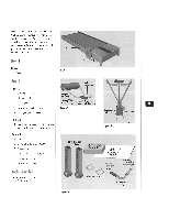
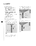
6. Repeat steps 2 through 5 with the other elevation leg. Be sure to set the legs at the same level. Figure 4 shows the front elevation legs and easy-lock pins properly installed. Easy-lock pins Figure 4 Attach the Upper-Body Exerciser 1. Locate the sensor cord coining from the bottom of the upper-body exerciser. Enwrap the cord so it hangs free and straight.. 2. Locale the tension cable hanging from the bottom of the upper-body exerciser: the tension cable has a spring attached to it. 3. Position the upper-body exerciser over the front of the treadmill base (Figure 5). The workout computer faceplate and the treadmill-tension control knob at the top of the upper-body exerciser should face the rear of Ihe treadmill deck, 4. Insert the sensor cord and tension cable through the opening between the wood panels in the treadmill base (Figure 5). 5. Align the four holes in the upper-body exerciser with the [bur holes in the treadmill base, NOTE: Be sure that the sensor cord and tension cable are not pinched between the treadmill base and the upper-body exerciser. 6. Insert the four bolts into the holes of the upperbody exerciser. Partially finger tighten each bolt as you insert it. NOTE: Insert and partially tighten oil four bolts before any one of the bolts is completely tightened. 7. Tighten the bolts with the 3/16-inch Allen wrench (Figure 6). Tension cable and spring Figure 5 Sensor cord Opening Figure 6 8. Make sure the snap buttons at the bottom of the upright tube are fully extended on both sides of the upright-tube support and locked in place.
-
 1
1 -
 2
2 -
 3
3 -
 4
4 -
 5
5 -
 6
6 -
 7
7 -
 8
8 -
 9
9 -
 10
10 -
 11
11 -
 12
12 -
13
-
14
-
15
-
16
-
17
-
18
-
19
-
20
-
21
-
22
-
23
-
24
-
25
-
26
-
27
-
28
-
29
-
30
 |
 |
