Onkyo HT-SR800 Owner Manual - Page 21
Wall Mounting, Speaker Set A supplied, Speaker Set B, Front speaker, SKF-550F, Surround - speakers
 |
View all Onkyo HT-SR800 manuals
Add to My Manuals
Save this manual to your list of manuals |
Page 21 highlights
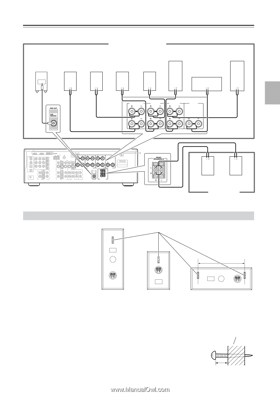
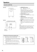
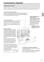
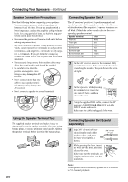
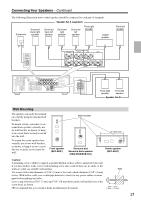
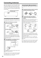
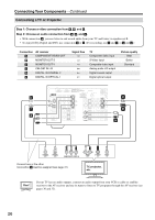
Connecting Your Speakers-Continued The following illustration shows which speaker should be connected to each pair of terminals. Speaker Set A (supplied) Subwoofer Surround back right speaker Surround back left speaker Surround right speaker Surround left speaker Front right speaker Center speaker LINE INPUT Front left speaker SURROUND BACK SPEAKERS L SURROUND SPEAKERS FRONT SPEAKERS A L CENTER SPEAKER R R DIGITAL IN ASSIGNABLE COAXIAL 1 (DVD) 2 (CBL/SAT) OPTICAL 1 (VCR/DVR) 2 (CD) IN 2 IN 1 HDMI OUT ASSIGNABLE AM ANTENNA FM 75 SIRIUS XM L Y CB/PB CR/PR CBL/SAT IN VCR/DVR IN DVD IN OUT COMPONENT VIDEO IN OUT IN L L CBL/SAT V VCR/DVR S IN OUT IN IN OUT IN L DVD MONITOR OUT V R S SURROUND BACK IN SPEAKERS FRONT SURROUND CENTER SURR BACK L REMOTE CONTROL R CD R TAPE R CBL/SAT VCR/DVR R SUB WOOFER DVD L R SURROUND SPEAKERS PRE OUT SUB WOOFER FRONT SPEAKERS A L CENTER SPEAKER R FRONT SPEAKERS B Front right speaker Front left speaker Speaker Set B Wall Mounting The speakers can easily be mounted on a wall by using the attached wall brackets. To mount a front, surround, or surround back speaker vertically, use its wall bracket, as shown, to hang it on a screw that's securely screwed into the wall. To mount the center speaker horizontally, use its two wall brackets, as shown, to hang it on two screws that are securely screwed into the wall. Front speaker (SKF-550F) Wall brackets Surround and Surround back speaker (SKM-550S/SKB-550) 13" (330 mm) Center speaker (SKC-550C) Caution: A mounting screw's ability to support a speaker depends on how well it's anchored to the wall. If you have hollow walls, screw each mounting screw into a stud. If there are no studs, or the walls are solid, use suitable wall anchors. Use screws with a head diameter of 5/16" (9 mm) or less and a shank diameter of 1/8" (4 mm) or less. With hollow walls, use a cable/pipe detector to check for any power cables or water pipes before making any holes. Leave a gap of between 5/16" (7 mm) and 7/16" (10 mm) between the wall and the base of the screw head, as shown. (We recommend that you consult a home installation professional.) Wall 5/16" - 7/16" (7 mm) - (10 mm) 21
-
 1
1 -
2
-
3
-
4
-
5
-
6
-
7
-
8
-
9
-
10
-
11
-
12
-
13
-
14
-
15
-
 16
16 -
 17
17 -
 18
18 -
 19
19 -
 20
20 -
 21
21 -
 22
22 -
 23
23 -
 24
24 -
 25
25 -
 26
26 -
27
-
28
-
29
-
30
-
31
-
32
-
33
-
34
-
35
-
36
-
37
-
38
-
39
-
40
-
41
-
42
-
43
-
44
-
45
-
46
-
47
-
48
-
49
-
50
-
51
-
52
-
53
-
54
-
55
-
56
-
57
-
58
-
59
-
60
-
61
-
62
-
63
-
64
-
65
-
66
-
67
-
68
-
69
-
70
-
71
-
72
 |
 |