Pioneer SEP C1 Owner's Manual - Page 9
Connections - software controller
 |
UPC - 012562891903
View all Pioneer SEP C1 manuals
Add to My Manuals
Save this manual to your list of manuals |
Page 9 highlights
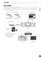
English CONNECTIONS CONNECTIONS Use the accessory USB auxiliary power cable and the normal USB cable to connect the unit to the computer (connect the USB auxiliary power cable first). Computer Accessory USB cable Accessory USB auxiliary power cable. PC 5V MONITOR OUT REMOTE CONTROL Audio interface (sold separately) Audio cable Mixer Do not connect the USB auxiliary power cable or USB cable until the driver software has been installed in the computer. NOTE • Do not connect anything to the 5 V connector other than the accessory USB auxiliary power cable. • Always use the accessory USB auxiliary power cable and USB cable only. • Always connect the accessory USB auxiliary power cable and USB cable to one and the same computer. • Do not connect this unit to a computer through a USB hub. • Do not connect this unit to a computer through a CardBus-supported USB interface card. Connection to external monitor (pin-jack connector) Use these connections when you wish to output the center display images to a large screen. After connecting this unit to the external monitor, the unit's settings must be changed (see the item "MONITOR OUT" in the topic "[1] DISPLAY" under the section "USING THE UTILITY" on P. 25). PC 5V MONITOR OUT REMOTE CONTROL External monitor 9 En
-
 1
1 -
2
-
3
-
 4
4 -
 5
5 -
 6
6 -
 7
7 -
 8
8 -
 9
9 -
 10
10 -
 11
11 -
 12
12 -
 13
13 -
 14
14 -
15
-
16
-
17
-
18
-
19
-
20
-
21
-
22
-
23
-
24
-
25
-
26
-
27
-
28
-
29
-
30
-
31
-
32
-
33
-
34
-
35
-
36
-
37
-
38
-
39
-
40
-
41
-
42
-
43
-
44
-
45
-
46
-
47
-
48
-
49
-
50
-
51
-
52
-
53
-
54
-
55
-
56
-
57
-
58
-
59
-
60
-
61
-
62
-
63
-
64
-
65
-
66
-
67
-
68
-
69
-
70
-
71
-
72
-
73
-
74
-
75
-
76
-
77
-
78
-
79
-
80
-
81
-
82
-
83
-
84
-
85
-
86
-
87
-
88
-
89
-
90
-
91
-
92
-
93
-
94
-
95
-
96
-
97
-
98
-
99
-
100
-
101
-
102
-
103
-
104
-
105
-
106
-
107
-
108
-
109
-
110
-
111
-
112
-
113
-
114
-
115
-
116
-
117
-
118
-
119
-
120
-
121
-
122
-
123
-
124
-
125
-
126
-
127
-
128
-
129
-
130
-
131
-
132
-
133
-
134
-
135
-
136
-
137
-
138
-
139
-
140
-
141
-
142
-
143
-
144
-
145
-
146
-
147
-
148
-
149
-
150
-
151
-
152
-
153
-
154
-
155
-
156
-
157
-
158
-
159
-
160
-
161
-
162
-
163
-
164
-
165
-
166
-
167
-
168
-
169
-
170
-
171
-
172
-
173
-
174
-
175
-
176
-
177
-
178
-
179
-
180
-
181
-
182
-
183
-
184
-
185
-
186
-
187
-
188
-
189
-
190
-
191
-
192
-
193
-
194
-
195
-
196
-
197
-
198
-
199
-
200
-
201
-
202
-
203
-
204
-
205
-
206
-
207
-
208
-
209
-
210
-
211
-
212
-
213
-
214
-
215
-
216
-
217
-
218
-
219
-
220
-
221
-
222
-
223
-
224
-
225
-
226
-
227
-
228
-
229
-
230
-
231
-
232
-
233
-
234
-
235
-
236
-
237
-
238
-
239
-
240
-
241
 |
 |
