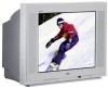
RCA 36F530T User Guide & Warranty - Page 6
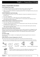
Connections & Setup
 |
UPC - 034909312421
View all RCA 36F530T manuals
Add to My Manuals
Save this manual to your list of manuals |
Page 6 highlights
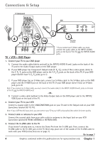
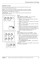
Connections & Setup TV (back panel) INPUT2 VIDEO R-AUDIO-L VCR Y PB PR INPUT1 VIDEO R-AUDIO-L CABLE/ ANTENNA AUDIO OUT G-LINK R L S-VIDEO 2 4 1B 1D 1A DVD 1C* OUT TO TV IN FROM ANT VIDEO AUDIO CH3 OUT CH4 R L IN R L 3 From Cable or Antenna OUT Y Pb Pr VIDEO R L S-VIDEO TV + VCR + DVD Player * If you connect an S-Video cable, you must connect the audio cables to the INPUT1 AUDIO jacks on the back of the TV, not the INPUT2 AUDIO jacks. 1. Connect your TV to your DVD player A. Connect the audio cables (white and red) to the INPUT2 AUDIO R and L jacks on the back of the TV and to the Audio Output Jacks on the DVD player. B. If your DVD player has Component Output Jacks (Y, PB, PR), connect three video grade cables to the Y, PB, PR jacks on the DVD player and to the Y, PB, PR jacks on the back of the TV. If your DVD player doesn't have Y, PB, PR jacks, go to C. -OR- C. If your DVD player has an S-Video jack, connect an S-Video cable to the S-Video jack on the DVD player and the S-VIDEO jack on the back of the TV. If your DVD player doesn't have an S-Video jack, go to D. Note: If you connect an S-Video cable, you must connect the audio cables to the INPUT1 AUDIO R and L jacks on the back of the TV, not the INPUT2 AUDIO jacks. -OR- D. Connect a video cable (yellow) to the Video Output Jack on the DVD player and to the INPUT2 VIDEO jack on the back of the TV. 2. Connect your TV to your VCR Connect a coaxial cable to the CABLE/ANTENNA jack on your TV and to the Output Jack on your VCR (sometimes labeled OUT TO TV). Note: If your VCR has A/V input jacks, you can connect your TV to your VCR using audio/video cables for better quality. 3. Connect cable or antenna to your VCR Connect the coaxial cable from your cable outlet or antenna to the Input Jack on your VCR (sometimes labeled IN FROM ANTENNA or IN FROM ANT). 4. Connect the G-LINK cable to the TV If you haven't already done so, remove the Demo Pin from the G-LINK jack. Then, connect the G-LINK cable to the G-LINK jack on the TV. Next step, place one of the wands of the G-LINK cable to work with your VCR (instructions are on page 7). Go to page 7 4 Graphics contained within this publication are for representation only. Chapter 1
-
 1
1 -
 2
2 -
 3
3 -
 4
4 -
 5
5 -
 6
6 -
 7
7 -
 8
8 -
 9
9 -
 10
10 -
 11
11 -
 12
12 -
13
-
14
-
15
-
16
-
17
-
18
-
19
-
20
-
21
-
22
-
23
-
24
-
25
-
26
-
27
-
28
-
29
-
30
-
31
-
32
-
33
-
34
-
35
-
36
-
37
-
38
-
39
-
40
-
41
-
42
-
43
-
44
-
45
-
46
-
47
-
48
-
49
-
50
-
51
-
52
-
53
-
54
-
55
-
56
-
57
-
58
-
59
-
60
-
61
-
62
-
63
-
64
-
65
-
66
-
67
-
68
-
69
-
70
-
71
-
72
-
73
-
74
-
75
-
76
-
77
-
78
-
79
-
80
-
81
-
82
-
83
-
84
-
85
-
86
-
87
-
88
-
89
-
90
-
91
-
92
-
93
-
94
-
95
-
96
 |
 |
