Sharp XR-32SL XR-32S XR-32X Operation Manual - Page 59
Connecting Pin Assignments
 |
UPC - 074000365582
View all Sharp XR-32SL manuals
Add to My Manuals
Save this manual to your list of manuals |
Page 59 highlights
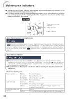
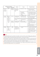
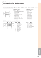
Connecting Pin Assignments COMPUTER/COMPONENT input and COMPUTER/COMPONENT output Terminals : mini Dsub 15 pin female connector 11 15 1 5 6 10 COMPUTER Input/Output Pin No. Signal 1. Video input (red) 2. Video input (green/sync on green) 3. Video input (blue) 4. Not connected 5. Not connected 6. Earth (red) 7. Earth (green/sync on green) 8. Earth (blue) 9. Not connected 10. GND 11. Not connected 12. Bi-directional data 13. Horizontal sync signal: TTL level 14. Vertical sync signal: TTL level 15. Data clock COMPONENT Input/Output Pin No. Signal 1. PR (CR) 2. Y 3. PB (CB) 4. Not connected 5. Not connected 6. Earth (PR) 7. Earth (Y) 8. Earth (PB) 9. Not connected 10. Not connected 11. Not connected 12. Not connected 13. Not connected 14. Not connected 15. Not connected DVI-D Terminal : 24 pin connector (XR-32X only) 24 17 Pin No. Signal 1. T.M.D.S data 2- 2. T.M.D.S data 2+ 3. T.M.D.S data 2 shield 4. Not connected 5. Not connected 6. DDC clock 7. DDC data 8. Not connected 8 1 9. T.M.D.S data 1- 10. T.M.D.S data 1+ 16 9 11. T.M.D.S data 1 shield 12. Not connected 13. Not connected 14. +5V power 15. Ground Pin No. Signal 16. Hot plug detection 17. T.M.D.S data 0- 18. T.M.D.S data 0+ 19. T.M.D.S data 0 shield 20. Not connected 21. Not connected 22. T.M.D.S clock shield 23. T.M.D.S clock+ 24. T.M.D.S clock- Appendix 55
-
 1
1 -
2
-
3
-
4
-
5
-
6
-
7
-
8
-
9
-
10
-
11
-
12
-
13
-
14
-
15
-
16
-
17
-
18
-
19
-
20
-
21
-
22
-
23
-
24
-
25
-
26
-
27
-
28
-
29
-
30
-
31
-
32
-
33
-
34
-
35
-
36
-
37
-
38
-
39
-
40
-
41
-
42
-
43
-
44
-
45
-
46
-
47
-
48
-
49
-
50
-
51
-
52
-
53
-
 54
54 -
 55
55 -
 56
56 -
 57
57 -
 58
58 -
 59
59 -
 60
60 -
 61
61 -
 62
62 -
 63
63 -
 64
64 -
65
-
66
-
67
-
68
-
69
-
70
-
71
-
72
-
73
 |
 |