Sharp XR-32SL XR-32S XR-32X Operation Manual - Page 60
Connecting Pin Assignments Continued
 |
UPC - 074000365582
View all Sharp XR-32SL manuals
Add to My Manuals
Save this manual to your list of manuals |
Page 60 highlights
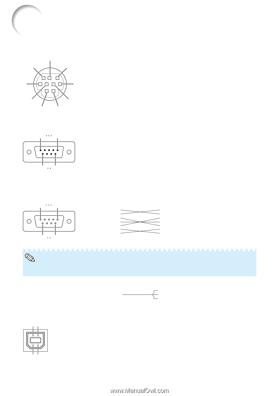
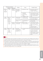
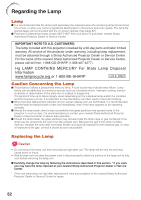
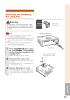
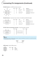
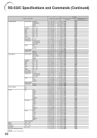
Connecting Pin Assignments (Continued) RS-232C Terminal : mini DIN 9 pin female connector 8 Pin No. Signal Name I/O 1. 9 7 2. RD Receive Data Input 3. SD Send Data Output 4. 5. SG Signal Ground 6 3 6. 7. RS Request to Send 8. CS Clear to Send 9. 5 4 2 1 Reference Not connected Connected to internal circuit Connected to internal circuit Not connected Connected to internal circuit Not connected Connected to CS in internal circuit Connected to RS in internal circuit Not connected RS-232C Terminal : D-sub 9 pin male connector of the DIN-D-sub RS-232C adaptor 1 5 69 Pin No. 1. 2. 3. 4. 5. 6. 7. 8. 9. Signal RD SD SG RS CS Name I/O Receive Data Send Data Input Output Signal Ground Request to Send Clear to Send Reference Not connected Connected to internal circuit Connected to internal circuit Not connected Connected to internal circuit Not connected Connected to CS in internal circuit Connected to RS in internal circuit Not connected RS-232C Cable recommended connection : D-sub 9 pin female connector 5 1 96 Pin No. Signal 1. CD 2. RD 3. SD 4. ER 5. SG 6. DR 7. RS 8. CS 9. CI Pin No. 1. 2. 3. 4. 5. 6. 7. 8. 9. Signal CD RD SD ER SG DR RS CS CI Note • Depending on the controlling device used, it may be necessary to connect Pin 4 and Pin 6 on the controlling device (e.g. computer). Projector Pin No. 4 5 6 Computer Pin No. 4 5 6 USB Terminal : Type B USB connector 43 Pin No. Signal Name 1. VCC USB power 2. USB- USB data- 3. USB+ USB data+ 4. SG Signal Ground 12 56
-
 1
1 -
2
-
3
-
4
-
5
-
6
-
7
-
8
-
9
-
10
-
11
-
12
-
13
-
14
-
15
-
16
-
17
-
18
-
19
-
20
-
21
-
22
-
23
-
24
-
25
-
26
-
27
-
28
-
29
-
30
-
31
-
32
-
33
-
34
-
35
-
36
-
37
-
38
-
39
-
40
-
41
-
42
-
43
-
44
-
45
-
46
-
47
-
48
-
49
-
50
-
51
-
52
-
53
-
54
-
 55
55 -
 56
56 -
 57
57 -
 58
58 -
 59
59 -
 60
60 -
 61
61 -
 62
62 -
 63
63 -
 64
64 -
 65
65 -
66
-
67
-
68
-
69
-
70
-
71
-
72
-
73
 |
 |