Sony CX150 Operating Instructions - Page 62
surface of this projector and the center of the screen - vpl ceiling mount
 |
UPC - 027242728158
View all Sony CX150 manuals
Add to My Manuals
Save this manual to your list of manuals |
Page 62 highlights
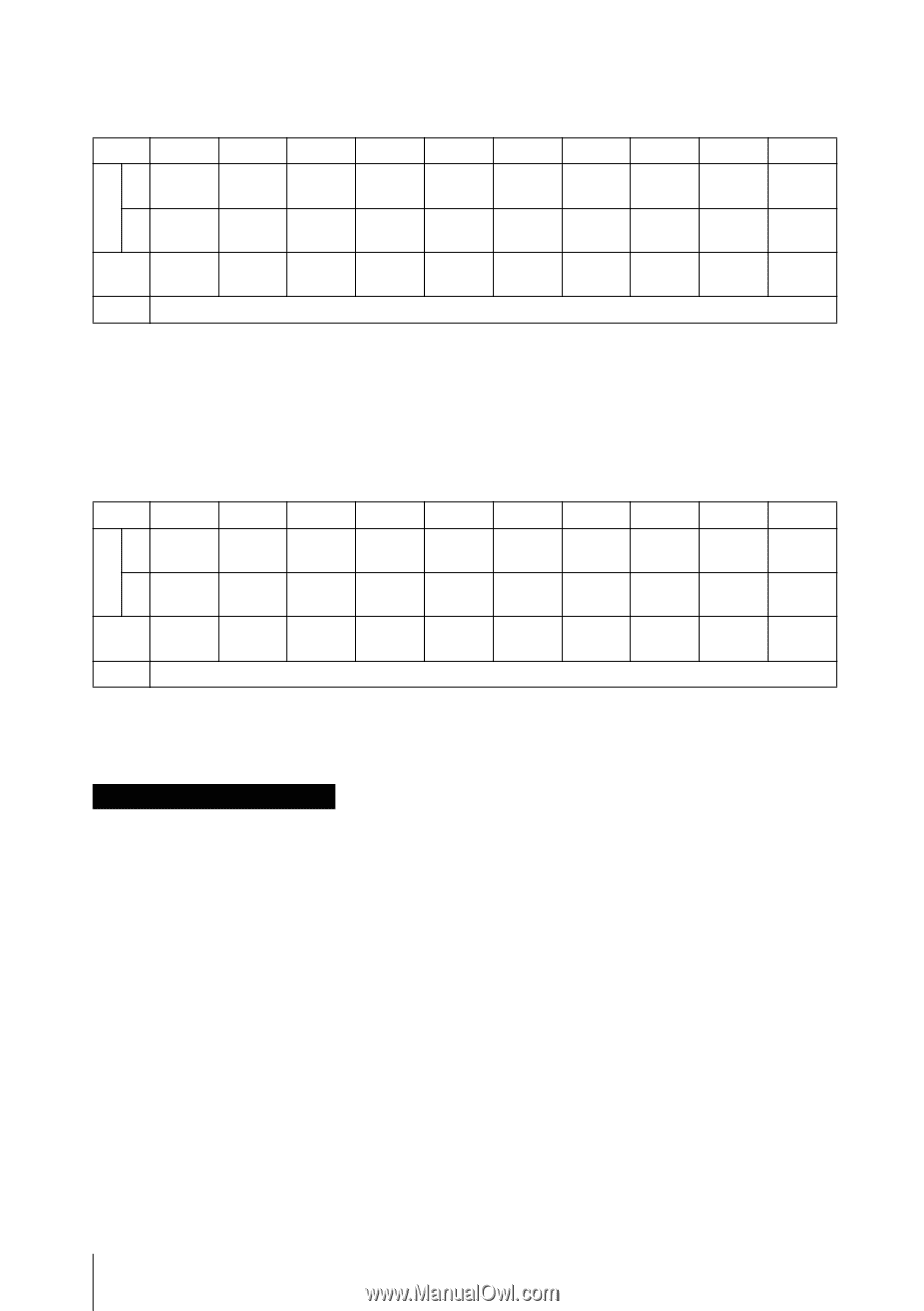
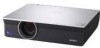
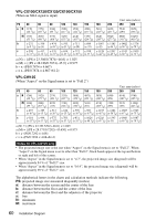
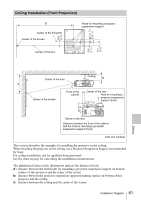
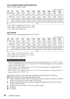
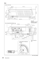
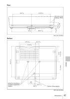
VPL-CX100/CX120/CX125/CX150/CX155 (When an XGA signal is input) Unit: mm (inches) PS 40 60 80 100 120 150 180 200 250 300 a' N 1290 1900 2500 3110 3720 4630 5540 6140 7660 9180 (50 25/32) (74 7/8) (98 1/2) (122 1/2) (146 1/2) (182 3/8) (218 1/4) (241 7/8) (301 5/8) (361 1/2) M 1470 2170 2870 3560 4260 5310 6360 7050 8800 10540 (57 7/8) (85 1/2) (113 1/8) (140 1/4) (167 3/4) (209 1/8) (250 1/2) (277 5/8) (346 1/2) (415 1/8) x b+290 b+409 b+527 b+646 b+764 b+942 b+1120 b+1239 b+1535 b+1831 (b+11 1/2) (b+16 1/8) (b+20 3/4) (b+25 1/2) (b+30 1/8) (b+37 1/8) (b+44 1/8) (b+48 7/8) (b+60 1/2) (b+72 1/8) b Free a'(N) = {(PS × 23.306/0.7874)+74.757} × 1.025 a'(M) = {(PS × 28.188/0.7874)+75.509} × 0.975 x = b + (PS/0.7874 × 4.667+53.2) VPL-CW125 (When "Aspect" on the Signal menu is set to "Full 2") Unit: mm (inches) PS 40 60 80 100 120 150 180 200 250 300 a N 1390 2040 2700 3350 (54 3/4) (80 3/8) (106 3/8) (132) 4010 4990 5970 6630 8260 9900 (157 29/32) (196 1/2) (235 3/8) (261 1/8) (325 1/4) (389 7/8) M 1580 2330 3090 3840 4590 5720 6850 7610 9490 11370 (621/4) (91 3/4) (121 3/4) (151 1/4) (180 3/4) (225 1/4) (269 3/4) (299 3/4) (373 3/4) (447 3/4) x b+310 b+438 b+567 b+695 b+823 b+1016 b+1208 b+1337 b+1658 b+1979 (b+12 1/4) (b+17 1/4) (b+22 3/8) (b+27 3/8) (b+32 1/2) (b+40) (b+47 5/8) (b+52 3/4) (b+65 3/8) (b+78) b Free a'(N) = {(PS × 23.3/0.7292)+75.145} × 1.025 a'(M) = {(PS × 28.171/0.7292)+75.75} × 0.975 x = b + (PS/0.7292 × 4.68+53.2) Notes for VPL-CW125 only • The projected image size is the one when "Aspect" on the Signal menu is set to "Full 2". When "Aspect" on the Signal menu is set to other than "Full 2", black bands appear at the top and bottom or right and left of the screen. • When "Aspect" in the Signal menu is set to "4:3", the projected image size (diagonal) will be approximately 84 % of "Full 2" size. • When "Aspect" in the Signal menu is set to "16:9", the projected image size (diagonal) will be approximately 99 % of "Full 2" size. The alphabetical letters in the charts and calculation methods indicate the following. PS: projected image size measured diagonally (inches) a': distance between the hole (front) for mounting a projector suspension support on bottom surface of this projector and the center of the screen b: distance between the projector suspension support mounting surface on bottom of this projector and the ceiling x: distance between the center of the screen and the ceiling N: minimum M: maximum 62 Installation Diagram
-
 1
1 -
2
-
3
-
4
-
5
-
6
-
7
-
8
-
9
-
10
-
11
-
12
-
13
-
14
-
15
-
16
-
17
-
18
-
19
-
20
-
21
-
22
-
23
-
24
-
25
-
26
-
27
-
28
-
29
-
30
-
31
-
32
-
33
-
34
-
35
-
36
-
37
-
38
-
39
-
40
-
41
-
42
-
43
-
44
-
45
-
46
-
47
-
48
-
49
-
50
-
51
-
52
-
53
-
54
-
55
-
56
-
 57
57 -
 58
58 -
 59
59 -
 60
60 -
 61
61 -
 62
62 -
 63
63 -
 64
64 -
 65
65 -
 66
66 -
 67
67 -
68
-
69
-
70
 |
 |