Toshiba MW27F51 Service Manual - Page 47
Electrical Adjustments
 |
View all Toshiba MW27F51 manuals
Add to My Manuals
Save this manual to your list of manuals |
Page 47 highlights
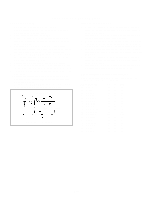
ELECTRICAL ADJUSTMENTS 1. BEFORE MAKING ELECTRICAL ADJUSTMENTS Read and perform these adjustments when repairing the circuits or replacing electrical parts or PCB assemblies. CAUTION • Use an isolation transformer when performing any service on this chassis. • Before removing the anode cap, discharge electricity because it contains high voltage. • When removing a PCB or related component, after unfastening or changing a wire, be sure to put the wire back in its original position. • When you exchange IC and Transistor with a heat sink, apply silicon grease on the contact section of the heat sink. Before applying new silicon grease, remove all the old silicon grease. (Old grease may cause damages to the IC and Transistor). Prepare the following measurement tools for electrical adjustments. 1. Oscilloscope 2. Digital Voltmeter 3. Multi-sound Generator 4. Pattern Generator On-Screen Display Adjustment 1. Set the VOLUME to minimum. 2. Press the VOL. DOWN button on the set and the Channel button (9) on the remote control for more than 2 seconds to appear the adjustment mode on the screen as shown in Fig. 1-1. TV 00 OSD 07 Fig. 1-1 3. Use the Channel UP/DOWN button or Channel button (09) on the remote control to select the options shown in Fig. 1-2. 4. Press the MENU button on the remote control to end the adjustments. NO. FUNCTION 00 OSD H 01 OSD C 02 03 H.POSI 04 H.BLK L 05 H.BLK R 06 V.SIZE 07 V.POSI 08 V. LIN 09 VS.CORR 10 V.COMP 11 R.BIAS 12 G.BIAS 13 B.BIAS 14 R.DRV 15 G.DRV 16 B.DRV 17 BRI CENT 18 BRI MAX 19 BRI MIN NO. FUNCTION 20 CONT CENT 21 CONT MAX 22 CONT MIN 23 COL CENT 24 COL. MAX 25 COL. MIN 26 TINT 27 SHARP 28 SUB BIAS 29 H. SIZE 30 PARABOLA 31 TRAPEZIUM 32 COR TOP 33 COR BTM 34 H. COMP 35 T.STE 36 37 38 H. FREQ 88 READ DATA Fig. 1-2 2. BASIC ADJUSTMENTS (VCR SECTION) 2-1: PG SHIFTER 1. Connect CH-1 on the oscilloscope to TP102 and CH-2 to TP4201. 2. Playback the alignment tape. 3. Press both VOL. DOWN button on the set and the Channel button (5) on the remote control for more than 2 seconds to set tracking to center. 4. Press the VOL. DOWN button on the set and the channel button (3) on the remote control for more than 2 seconds until the indicator REC disappears. If the indicator REC disappears, adjustment is completed. (If the above adjustments doesn't work well:) 5. Press the VOL. DOWN button on the set and the channel button (3) on the remote control for more than 2 seconds until the indicator REC disappears. 6. When the REC indicator is blinking, press both VOL. DOWN button on the set and the channel button (4) on the remote control for more than 2 seconds and adjust the Tracking +/- button until the arising to the down of Head Switching Pulse becomes 6.5 ± 0.5H. (Refer to Fig. 2-1-A, B) CH-2 6.5H CH-1 Fig. 2-1-A CH-2 D3-1 CH-1 6.5H Fig. 2-1-B
-
 1
1 -
2
-
3
-
4
-
5
-
6
-
7
-
8
-
9
-
10
-
11
-
12
-
13
-
14
-
15
-
16
-
17
-
18
-
19
-
20
-
21
-
22
-
23
-
24
-
25
-
26
-
27
-
28
-
29
-
30
-
31
-
32
-
33
-
34
-
35
-
36
-
37
-
38
-
39
-
40
-
41
-
 42
42 -
 43
43 -
 44
44 -
 45
45 -
 46
46 -
 47
47 -
 48
48 -
 49
49 -
 50
50 -
 51
51 -
 52
52 -
53
-
54
-
55
-
56
-
57
-
58
-
59
-
60
-
61
-
62
-
63
-
64
-
65
-
66
-
67
-
68
-
69
-
70
-
71
-
72
-
73
-
74
-
75
-
76
-
77
-
78
-
79
-
80
-
81
-
82
-
83
-
84
-
85
-
86
-
87
-
88
-
89
-
90
-
91
-
92
-
93
-
94
-
95
-
96
-
97
-
98
-
99
-
100
-
101
-
102
-
103
-
104
-
105
-
106
-
107
-
108
-
109
-
110
 |
 |
