Toshiba MW27F51 Service Manual - Page 51
Purity And Convergence, Adjustments
 |
View all Toshiba MW27F51 manuals
Add to My Manuals
Save this manual to your list of manuals |
Page 51 highlights
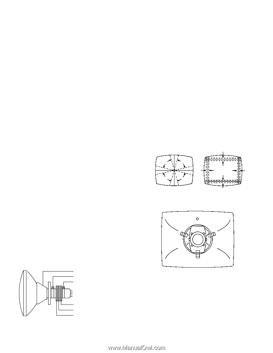
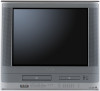
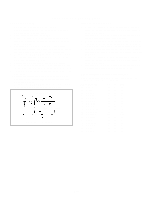
ELECTRICAL ADJUSTMENTS 3. PURITY AND CONVERGENCE ADJUSTMENTS NOTE 1. Turn the unit on and let it warm up for at least 30 minutes before performing the following adjustments. 2. Place the CRT surface facing east or west to reduce the terrestrial magnetism. 3. Turn ON the unit and demagnetize with a Degauss Coil. 3-1: STATIC CONVERGENCE (ROUGH ADJUSTMENT) 1. Tighten the screw for the magnet. Refer to the adjusted CRT for the position. (Refer to Fig. 3-1) If the deflection yoke and magnet are in one body, untighten the screw for the body. 2. Receive the green raster pattern from the color bar generator. 3. Slide the deflection yoke until it touches the funnel side of the CRT. 4. Adjust center of screen to green, with red and blue on the sides, using the pair of purity magnets. 5. Switch the color bar generator from the green raster pattern to the crosshatch pattern. 6. Combine red and blue of the 3 color crosshatch pattern on the center of the screen by adjusting the pair of 4 pole magnets. 7. Combine red/blue (magenta) and green by adjusting the pair of 6 pole magnets. 8. Adjust the crosshatch pattern to change to white by repeating steps 6 and 7. 3-2: PURITY NOTE Adjust after performing adjustments in section 3-1. 1. Receive the green raster pattern from color bar generator. 2. Adjust the pair of purity magnets to center the color on the screen. Adjust the pair of purity magnets so the color at the ends are equally wide. 3. Move the deflection yoke backward (to neck side) slowly, and stop it at the position when the whole screen is green. 4. Confirm red and blue colors. 5. Adjust the slant of the deflection yoke while watching the screen, then tighten the fixing screw. DEFLECTION YOKE DEFLECTION YOKE SCREW MAGNET SCREW 3-3: STATIC CONVERGENCE NOTE Adjust after performing adjustments in section 3-2. 1. Receive the crosshatch pattern from the color bar generator. 2. Combine red and blue of the 3 color crosshatch pattern on the center of the screen by adjusting the pair of 4 pole magnets. 3. Combine red/blue (magenta) and green by adjusting the pair of 6 pole magnets. 3-4: DYNAMIC CONVERGENCE NOTE Adjust after performing adjustments in section 3-3. 1. Adjust the differences around the screen by moving the deflection yoke upward/downward and right/left. (Refer to Fig. 3-2-a) 2. Insert three wedges between the deflection yoke and CRT funnel to fix the deflection yoke. (Refer to Fig. 3-2-b) R G B R G B R G B R G B UPWARD/DOWNWARD SLANT Fig. 3-2-a RIGHT/LEFT SLANT WEDGE WEDGE WEDGE WEDGE POSITION Fig. 3-2-b 6 POLE MAGNETS 4 POLE MAGNETS PURITY MAGNETS Fig. 3-1 D3-5
-
 1
1 -
2
-
3
-
4
-
5
-
6
-
7
-
8
-
9
-
10
-
11
-
12
-
13
-
14
-
15
-
16
-
17
-
18
-
19
-
20
-
21
-
22
-
23
-
24
-
25
-
26
-
27
-
28
-
29
-
30
-
31
-
32
-
33
-
34
-
35
-
36
-
37
-
38
-
39
-
40
-
41
-
42
-
43
-
44
-
45
-
 46
46 -
 47
47 -
 48
48 -
 49
49 -
 50
50 -
 51
51 -
 52
52 -
 53
53 -
 54
54 -
 55
55 -
 56
56 -
57
-
58
-
59
-
60
-
61
-
62
-
63
-
64
-
65
-
66
-
67
-
68
-
69
-
70
-
71
-
72
-
73
-
74
-
75
-
76
-
77
-
78
-
79
-
80
-
81
-
82
-
83
-
84
-
85
-
86
-
87
-
88
-
89
-
90
-
91
-
92
-
93
-
94
-
95
-
96
-
97
-
98
-
99
-
100
-
101
-
102
-
103
-
104
-
105
-
106
-
107
-
108
-
109
-
110
 |
 |